|
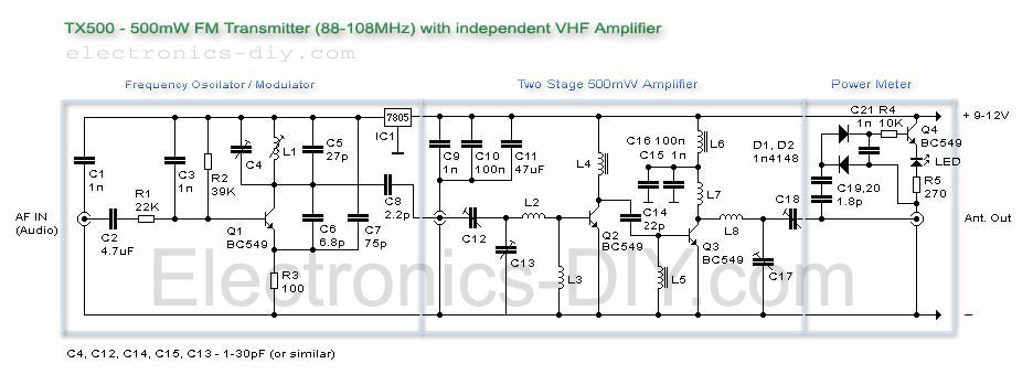
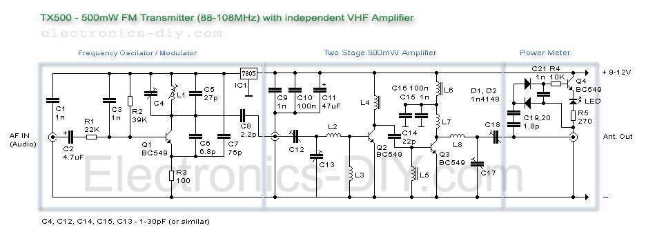
Click on the image to enlarge the schematic.
| Please
be advised that it might be illegal to use this transmitter.
This project is presented here only for educational
purposes. |
About
TX500 - 500mW FM Transmitter
| |
The
TX500 is a simple to build 500mW FM Transmitter. It
consists of three blocks; modulator / oscillator,
two stage 500mW VHF amplifier and LED based power
meter. The TX500 allows to transmit audio signals
to FM band at frequencies from 88 MHz to 108 MHz.
Due to the very low power consumption of less than
100mA the circuit may be perfectly powered by using
9-12V battery or power supply if you prefer. The circuit
has been divided into separate stages so that it is
be better for everyone to understand how every part
works independently. |
Transistors
| |
Notice
that all of the transmitter blocks have been built
using four low noise general purpose NPN transistors.
These transistors should be easy to find. Most of
the regular NPN transistors should work fine and these
are just some of the examples: BC549 (low noise),
2n2222, BC109 (low noise), BC107, etc. Please be aware
that audio power transistors like BD140, 2n3055, TIP3055,
2SC5200 and such will not work because they can not
handle higher frequencies. Thanks to the fact that
the regular NPN can work at 100MHz and above we can
use them in all of the lower power blocks of FM transmitters.
If
you prefer you may also use RF transistors like BF199,
MPSH10, BF240, etc.
|
How
FM Transmitter Works
| |
Stability
The first block of TX500 based around transistor Q1
- BC549 acts as a simple modulator / oscillator. Many
of the low cost FM transmitters use very similar circuit
to generate radio signals but this oscillator has
been carefully improved to provide much better stability.
First thing that does make a great difference is the
use of a tunable
coil for L1 as opposed to a regular air coil.
The use of this kind of coil allows for precise tuning
of a desired frequency which is especially important
on crowded FM bands. An issue with an air based coils
is that it is much more difficult to tune-in to a
specific frequency and usually more time is needed
to set such oscillator to a desired frequency. Another
advantage of tunable
coil is that its coil is very firm and thus much
more resistive to frequency drifts caused by an temperature
changes. These type of oscillators are also prone
to frequency drifts caused by unstable supply voltages.
This refers both to a batteries and DC power supplies
as well. To help solve this problem an IC1 - 5V regulator
is used to power an oscillator.
Oscillator
The carrier frequency of an oscillator is determined
by the capacity of C4, C5 in conjunction with the
inductance of the coil L1. 3.5 turns are needed and
27pF for C5 to tune to a lower part of FM band (88-100MHz).
To be able to tune to a higher part (100-108MHz) you
can use a 10pF capacitor. C6 is necessary for Q1 to
keep oscillating and C7 helps in frequency tuning.
R1 - 100 Ohm has been selected to provide a clear
oscillation of a frequency. Do not get tempted to
use much lower resistance or to remove it completely
because that would bring instability and generation
of unwanted frequencies around the main carrier frequency.
C8 is the final and very important element. Its job
is to both separate an oscillator from the rest of
the blocks to prevent a frequency drifts and 2.2pF
is just enough to pass an oscillator's signal to an
amplifier. Again, do not get tempted to use a larger
capacitance because that will not increase an output
power of the transmitter, it would in fact do the
opposite and cause undesired behavior.
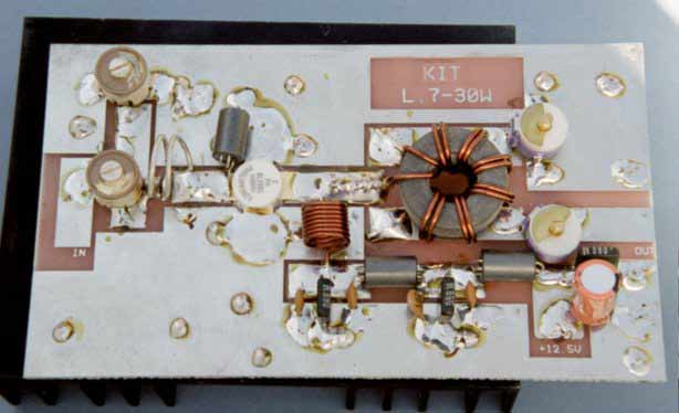
VHF Amplifier
 |
 |
|
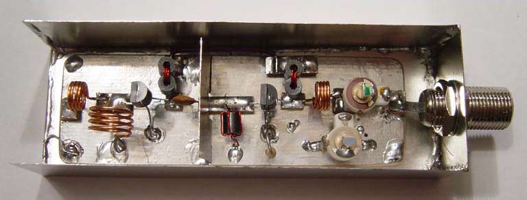
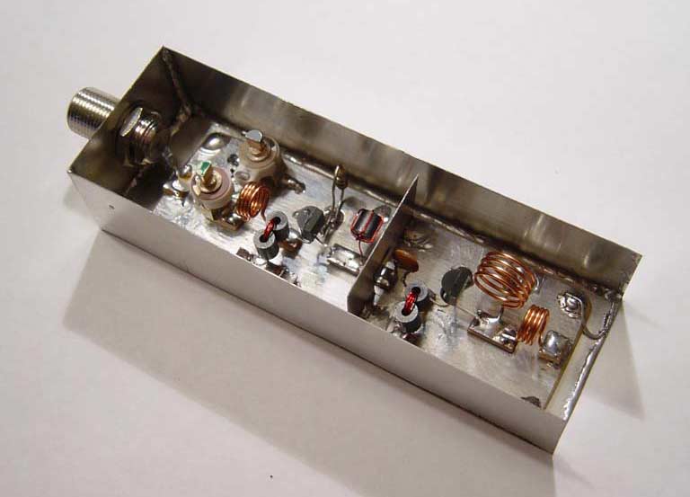
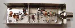
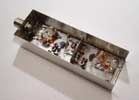
These
are some images from an early tests with
VHF amplifier.
|
|
This is the block that will give you a lot of fun
and teach you the basic concept of VHF amplifiers,
especially if you have never built one. Please do
not get discouraged if the schematic looks like
it has so many coils because they are very easy
to make. From the above picture of an early prototype
you can see one of the possible ways to build the
VHF amplifier. By doing it this way you will greatly
minimize the external noise that could otherwise
have been amplified along with the incoming signal
from the oscillator. What you will need is copper
PC board as the main board and small pieces of PC
bard that serve as interconnections between the
components. As you can notice the driver is also
separated by a metal plate that is soldered to the
ground. All these additions will increase the overall
amplifier's quality because the amplified signal
from the output stage will not be bounced back to
the driver's stage. Another very crucial thing that
you should always keep in mind while designing a
good amplifier is that the coils should not be placed
too close to each other, always provide some minimal
air separation.
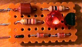
Power
Meter
With just a few components you may also build a
LED based RF meter that is extremely handy to check
for a presence and strength of a RF signal. The
power meter can be built on a tiny board 0.5"x1"
as shown below. It only needs three connectors;
RF input, voltage supply and a ground.
This meter will only detect high frequencies and
the strength of their signal. If there is no RF
activity the LED will not illuminate. You can even
connect its RF input to 12V and see that nothing
will happen because an input of the meter is separated
by two 1.8pF capacitors that will only pass RF signals.
To test and see if the meter works, simply connect
the first block (oscillator) to the power supply,
then connect the input of the meter to an output
of an oscillator and LED should illuminate at around
20% out its full brightness.
For the sake of efficiency two stage amplifier have
been used here. Transistor Q2 works as a driver
and Q3 as an output stage of an amplifier. One could
build an amplifier using just one single transistor
but in that case the transistor would not be able
to provide its maximum 500mW output power. That's
why most amplifiers use both a driver and an output
transistors.
The driver's job here is to take the fragile signal
coming out from an oscillator (Q1) and amplify it
to a required level before passing it to an output
transistor. Driver may be built with just one transistor
and it may use two, three or as many it is necessary.
The reason for this is that every transistor that
is used in an output stage needs a certain amount
of input power to achieve its peak output power.
You can't just plug-in an oscillator to one 1W,
10W or 100W transistor and expect to give its full
RF power. Every data sheet of a given transistor
should state what is a minimum power that is needed
to drive that given transistor. For example 1W transistor
like 2n4427 may need 150-300mW input signal, 2n3866
5W transistor at least 500mW, 10W transistor al
least 1W and 100W transistor at least 10W. You should
always keep that in mind while building a VHF amplifier.
If you take a look at amplifier's schematic you
may notice that driver and output transistor was
set to provide the maximum gain because there is
no resistor between the emitter of Q2, Q3 and the
ground. This was done to maximize an output power
of NPN transistors and because of that these transistors
may get a little warm but not hot). If in place
of Q2 and Q3 you decide to use some more powerful
transistors than you will definitely need to use
a small resistance resistor to protect them and
to minimize the heat dissipation. Driver should
have a resistor of larger resistance like 100 Ohms
depending on the voltage supply and the type of
transistor being used. Output transistor should
have a resistor with a lower resistance.
When amplifier is used and there is no incoming
RF signal it is simply in the "resting stage"
and power meter's LED should not illuminate. As
soon as the oscillator or small power transmitter
is connected power meter's LED will illuminate indicating
the presence of RF signal and giving you feedback
that amplifier is working properly.
Before
using a RF amplifier small tuning needs to be performed
so that amplifier can provide the maximum output
power. Adjust trimmers C12 and C13 so that LED illuminates
at its highest peak. Do the same for C17 and C18
trimmers. If you connect input of the power meter
to the capacitor C14 from an antenna output side
LED should illuminate at 50 - 60% of its full peak.
Now check an oscillator's output and notice how
RF signal is amplified. It is very easy to see that
RF signal is amplified gradually and this is the
way it should always be done. In stronger transmitters
when driver needs to provide more RF power, for
instance 1W, the signal is first amplified by small
signal transistors and passed on to the stronger
RF transistors.
You should also understand that RF amplifier will
amplify certain range of frequencies. Through using
specified amount of turns in the coils, amplifier
will amplify the desired frequencies (in our case
frequencies around 80-120MHz). With a small modifications
the same amplifier may be also used to amplify an
antenna's signal of your FM radio.
|
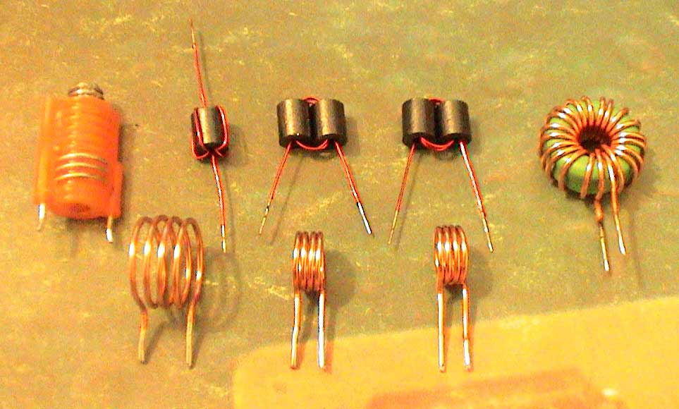
Coils
| |
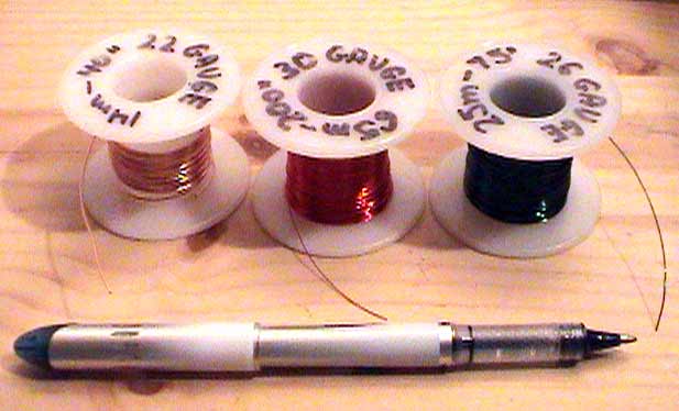
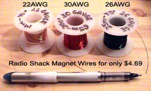
Required
Materials
These are materials that have been used to make coils
for TX500 transmitter. If you don't have any spare
magnet wires check Radio Shack. They sell three spools
of magnet wire for around $5. The coil pack purchased
from Radio Shack includes 14 meters of 22AWG (.065mm)
wire, 25 meters of 26AWG (0.4mm) wire and 65 meters
of 30AWG (0.25mm) wire.
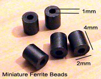
Miniature
ferrite beads are used for amplifier coils.If
you have difficulties finding ferrite beads you
may replace L4, L5, L7 coils with regular air coils
but keep in mind that ferrite based coils provide higher
output gain.
Here are the replacements:
L4, L5 - 4 turns / 5mm diameter / 0.5-1mm magnet wire
(exactly the same as L2,
L8 )
L5 - is the same as L4, L5 but should have 5 turns instead
of 4.

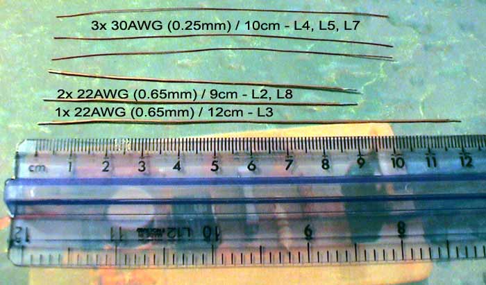
Cut
the magnet wires to suggested length.

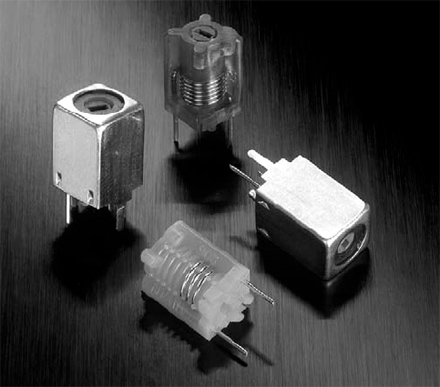
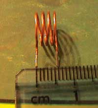
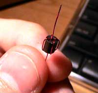
L1 Coil
Use 3.5 turns high precision variable coil (0.5mm /
24AWG magnet wire on 5mm diameter). Tunable RF coils
are ideal for precise frequency tuning of FM transmitter
throughout the entire FM band (88 - 108MHz). The magnet
wire is halfway embedded within the plastic providing
excellent frequency stability.
If
you have no access to variable coils you could try to
use a regular air coil. The wire thickness should be
around 1 mm and make sure to use resin it to make it
firm. Keep in mind air coils are not recommended for
oscillator coils because temperature changes will cause
frequency drifts.
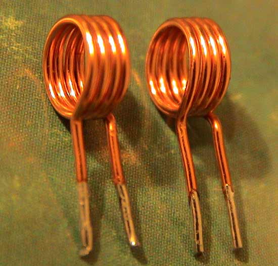
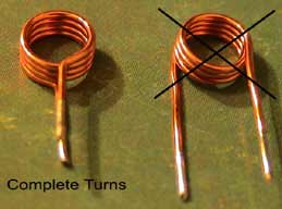
L2, L8 Coils
4 turns of 0.65mm / 22AWG magnet wire on 5mm
diameter.
1. Cut 9cm (3.5") of wire (1mm
- 0.2m / 18 - 30AWG wire is fine as well).
2. Make 4 complete turns a shown on the pictures.

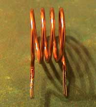
L3
Coil
4 turns of 0.65mm / 22AWG magnet wire on 9mm
diameter.
1. Cut 13cm (5") of magnet wire (1mm
- 0.2m / 18 - 30AWG wire is fine as well).
2. Make 4 complete turns (as in L2, L8) on a 9mm diameter
or a pencil.
3. Spread it to approximately 0.6mm
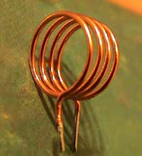
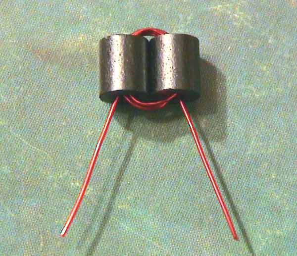
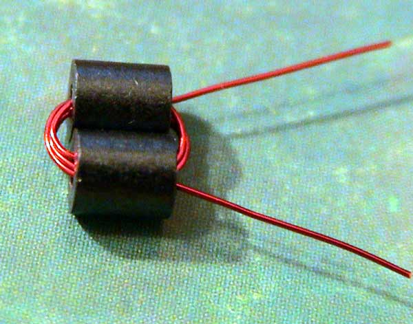
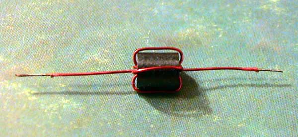
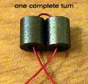
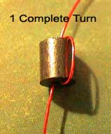
L4, L7 Coils
Wind 4 turns of 0.25mm / 30AWG magnet wire
on two small ferrite beads.
1.
Cut 9cm (3.5")
of magnet wire
2.
Make 4 turns. The first picture shows one complete turn,
four turns will be complete when you will see four wires
in the upper part.
These small beads are perfect to use in the transmitters
up to 1W. Larger ferrite beads and a thicker magnet
wire should be used for higher output transmitters.
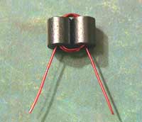

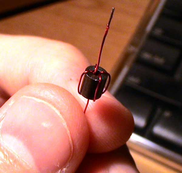
L5 Coil
4 turns on a single ferrite bead.
1. Cut 10cm of 0.25mm / 30AWG magnet wire.
2. Make 4 turns on one small ferrite bead as shown on
the pictures.

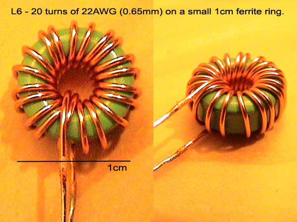
L6 Choke
20
turns of 0.65mm / 22AWG magnet wire on a ferrite ring.
This
is a 1.5 cm ferrite ring that can be found in computer
power supplies or motherboards. They may come in a different
colors but they certainly will do the same job.

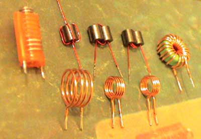
Pictures of finished coils that have been
used in TX500 transmitter.
|
Designing
the PC Board
| |
It
is recommended to use two 1" x 3" PCBs,
one for oscillator and the other one for VHF Amplifier.
This option will allow you to experiment with the
different oscillators / transmitters. While constructing
RF amplifier care must be taken to enclose both
oscillator and amplifier in the metal cases to minimize
external frequency noise.
|
Glossary
of Common Terms:
| |
FM
- Frequency Modulation
VFO - Variable Frequency Oscillator
VCO - Voltage Controlled Oscillator
PLL - Phase Locked Loop (digitally controlled
oscillator)
Oscillator - device that generates a frequency
Frequency Ranges:
VLF - Very Low Frequency (3KHz - 30KHz) - Surface
LF - Low Frequency (30KHz - 300KHz) - Surface
MF - Middle Frequency (300KHz - 3MHz) - Tropospheric
HF - High Frequency (3MHz - 30MHz) - Ionospheric
VHF
- Very High Frequency (30MHz - 300MHz) - Space
and line of sight
UHF - Ultra High Frequency (300MHz - 3GHz)
- Space and line of sight
SHF - Super High Frequency (3GHz - 30GHz) - Space
EHF - Extremely High Frequency (30GHz - 300GHz)
- Space
|
Where to get the Parts
| |
If you are building the above FM Transmitter and have trouble finding components such as variable coils, BC549 transistors or ferrite beads we are distributing these components in our Electronics-DIY store.
|
Related Links
|
|
|
| |
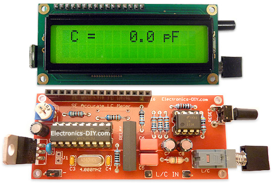
Accurate LC Meter
Build your own Accurate LC Meter (Capacitance Inductance Meter) and start making your own coils and inductors. This LC Meter allows to measure incredibly small inductances making it perfect tool for making all types of RF coils and inductors. LC Meter can measure inductances starting from 10nH - 1000nH, 1uH - 1000uH, 1mH - 100mH and capacitances from 0.1pF up to 900nF. The circuit includes an auto ranging as well as reset switch and produces very accurate and stable readings. |
|
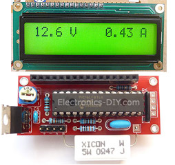
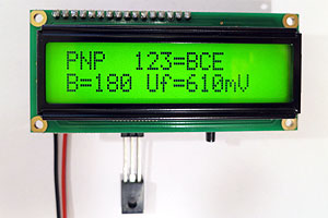
PIC Volt Ampere Meter
Volt Ampere Meter measures voltage of 0-70V or 0-500V with 100mV resolution and current consumption 0-10A or more with 10mA resolution. The meter is a perfect addition to any power supply, battery chargers and other electronic projects where voltage and current must be monitored. The meter uses PIC16F876A microcontroller with 16x2 backlighted LCD. |
|
|
|
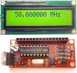
60MHz Frequency Meter / Counter
Frequency Meter / Counter measures frequency from 10Hz to 60MHz with 10Hz resolution. It is a very useful bench test equipment for testing and finding out the frequency of various devices with unknown frequency such as oscillators, radio receivers, transmitters, function generators, crystals, etc. |
|
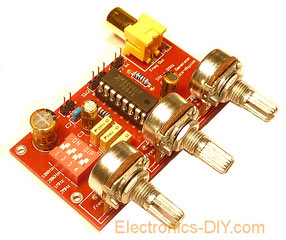
1Hz - 2MHz XR2206 Function Generator
1Hz - 2MHz XR2206 Function Generator produces high quality sine, square and triangle waveforms of high-stability and accuracy. The output waveforms can be both amplitude and frequency modulated. Output of 1Hz - 2MHz XR2206 Function Generator can be connected directly to 60MHz Counter for setting precise frequency output. |
|
|
|
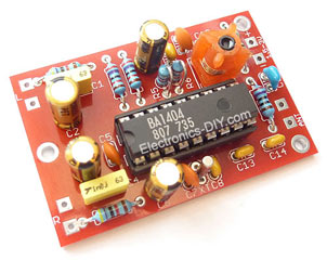
BA1404 HI-FI Stereo FM Transmitter
Be "On Air" with your own radio station! BA1404 HI-FI Stereo FM Transmitter broadcasts high quality stereo signal in 88MHz - 108MHz FM band. It can be connected to any type of stereo audio source such as iPod, Computer, Laptop, CD Player, Walkman, Television, Satellite Receiver, Tape Deck or other stereo system to transmit stereo sound with excellent clarity throughout your home, office, yard or camp ground. |
|
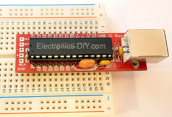
USB IO Board
USB IO Board is a tiny spectacular little development board / parallel port replacement featuring PIC18F2455/PIC18F2550 microcontroller. USB IO Board is compatible with Windows / Mac OSX / Linux computers. When attached to Windows IO board will show up as RS232 COM port. You can control 16 individual microcontroller I/O pins by sending simple serial commands. USB IO Board is self-powered by USB port and can provide up to 500mA for electronic projects. USB IO Board is breadboard compatible. |
|
|
|
|
ESR Meter / Capacitance / Inductance / Transistor Tester Kit
ESR Meter kit is an amazing multimeter that measures ESR values, capacitance (100pF - 20,000uF), inductance, resistance (0.1 Ohm - 20 MOhm), tests many different types of transistors such as NPN, PNP, FETs, MOSFETs, Thyristors, SCRs, Triacs and many types of diodes. It also analyzes transistor's characteristics such as voltage and gain. It is an irreplaceable tool for troubleshooting and repairing electronic equipment by determining performance and health of electrolytic capacitors. Unlike other ESR Meters that only measure ESR value this one measures capacitor's ESR value as well as its capacitance all at the same time. |
|
Audiophile Headphone Amplifier Kit
Audiophile headphone amplifier kit includes high quality audio grade components such as Burr Brown OPA2134 opamp, ALPS volume control potentiometer, Ti TLE2426 rail splitter, Ultra-Low ESR 220uF/25V Panasonic FM filtering capacitors, High quality WIMA input and decoupling capacitors and Vishay Dale resistors. 8-DIP machined IC socket allows to swap OPA2134 with many other dual opamp chips such as OPA2132, OPA2227, OPA2228, dual OPA132, OPA627, etc. Headphone amplifier is small enough to fit in Altoids tin box, and thanks to low power consumption may be supplied from a single 9V battery. |
|
|
|
|
|
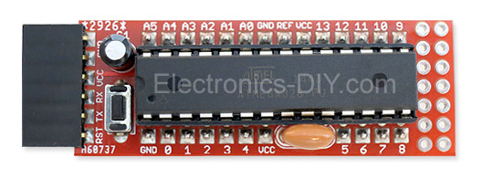
Arduino Prototype Kit
Arduino Prototype is a spectacular development board fully compatible with Arduino Pro. It's breadboard compatible so it can be plugged into a breadboard for quick prototyping, and it has VCC & GND power pins available on both sides of PCB. It's small, power efficient, yet customizable through onboard 2 x 7 perfboard that can be used for connecting various sensors and connectors. Arduino Prototype uses all standard through-hole components for easy construction, two of which are hidden underneath IC socket. Board features 28-PIN DIP IC socket, user replaceable ATmega328 microcontroller flashed with Arduino bootloader, 16MHz crystal resonator and a reset switch. It has 14 digital input/output pins (0-13) of which 6 can be used as PWM outputs and 6 analog inputs (A0-A5). Arduino sketches are uploaded through any USB-Serial adapter connected to 6-PIN ICSP female header. Board is supplied by 2-5V voltage and may be powered by a battery such as Lithium Ion cell, two AA cells, external power supply or USB power adapter. |
|
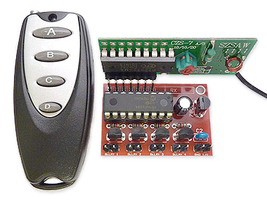
200m 4-Channel 433MHz Wireless RF Remote Control
Having the ability to control various appliances inside or outside of your house wirelessly is a huge convenience, and can make your life much easier and fun. RF remote control provides long range of up to 200m / 650ft and can find many uses for controlling different devices, and it works even through the walls. You can control lights, fans, AC system, computer, printer, amplifier, robots, garage door, security systems, motor-driven curtains, motorized window blinds, door locks, sprinklers, motorized projection screens and anything else you can think of. |
|
|
|