| |
Here is a simple TV transmitter. The circuit is simple and really quite crude, but it does include MONO sound. I have not shown the two regulators in the drawing. These are one 12v DC 1A series regulator chip, and one 8v DC 1A series regulator. I fed the 8v regulator from the output of the 12v regulator. The rest of the circuit looks like this. It is a free-running Variable Frequency Oscillator (VFO) using just one coil and one capacitor to determine the frequency. Change this as you will. The basic circuit uses a 150pf from the Base of the RF transistor to ground, so that TR2 operates as a "common-base mode" (grounded base) amplifier. The tuned circuit in the collector and the capacitor from collector to emitter provide tuning and feedback.
A low-impedance tapping of the coil drives TR3, which is a class-C amplifier. Unlike the V5 FM transmitter, this stage does provide RF amplification; about 14dB. It also buffers the antenna circuit from the oscillator, and is the stage that is modulated by means of the supply voltage.
The collector load of TR3 is untuned. The inductor is a ferrite bead with about three turns of wire through the little hole. You can use just about any old ferrite here, as long as it is a closed ring with the wire through the middle. The RF output level from this stage is in the order of 100mW and is filtered before feeding the antenna.
The values quoted in the circuit are all for 200MHz, Band-III. L2 (VHF choke) is three turns of wire through a small ferrite bead. One turn should work just as good as 6 turns, so this coil is not at all critical.
The Modulator
Modulation consists of 7v DC to power this stage, but with +/-4v of composite video superimposed on the DC level. If your DC out to TR2 is not 7v then select a different value for the 330R resistor. The video is inverted. Since the oscillator and amplifier stages are fed from a 12v DC stabilised supply, the modulation level is stable, so no adjustments are necessary. No contrast, level, sync - nuthin!. This is the way I like things to be.
The video input signal is first loaded with a 75-Ohm resistive load, then coupled to TR4 where it is amplified and inverted. The video gain is set by the 330R emitter resistor. If you really want to play about with the video levels then you can decouple this resistor with a 470uf electrolytic and a 1K0 preset pot. The collector of TR4 is just under +8v DC with no signal.
TR5 is a simple emitter-follower, or current buffer. This stage allows the collector of TR4 to become the modulated power source for TR3, thus providing amplitude modulation.
Note that there is NO clamping diode. The modulator is DC-coupled and therefore does not appear to need any level correction circuit. I tried it on three different cameras and all worked very well. I also found that some cameras need to have the resistive load, so a capacitive input did not work with all three of the ameras I used. If you do want to add a capacitive input then a 470uF is needed, as well as a diode across the load resistor - anode to ground. This will stop the DC level varying with changes of average video level.
The Sound Carrier
Sound is added back at the RF oscillator stage. TR2 needs to have a regulated supply to prevent frequency and amplitude variations. But if we add a low-level 5.5MHz signal across the 47pf base capacitor, then TR2 will become modulated with 5.5MHz. The 5.5MHz modulation is a very low level signal, so we can get-away with applying the sound sub-carrier here. It simplifies the modulator stage quite a lot.
TR1 is a simple 5.5MHz (6.0MHz) oscillator stage wound on a ferrite former. In this way it can be varied to suit your own countries sound IF standard. Here in Sweden it is 5.5MHz. The oscillator is a simple colpits design, having a varicap diode (varactor diode) to apply Frequency Modulation (FM) to the 5.5MHz carrier. I first injected the sound sub-carrier from my Marconi TF995 generator, but then I used a 10.7MHz IF can using the values shown in the diagram. The IF can internal capacitor is left in circuit (but not shown in the diagram).
Audio is controlled by VR1 to feed the varicap diode. I used a C16V0 Zener diode instead of the varicap, since they are cheap, and I have got a lot of them. You can use any Zener diode you like, as long as the avalanche voltage is under 10v. Because of the possible wide variations of diode, a preset pot is needed here to se the sound level.
I MUST add that the sound sub-carrier is still under construction, so regard TR1 as a provisional circuit. I also need to investigate the possibillity of adding stereo. I am not sure if there will be an update to this (in addition to the PCB), or a complete Mk-III project. Time will tell. It all depends upon where the mood takes me.
Alignment
Alignment is very important if you want to get a good result. I have tried to keep alignment down to a bare minimum, but you will still have to set the audio level and the transmitter frequency.
Set your TV to a blank channel with no signal, just a good old "war-of-the-ants", without any patterns. Adjust VC1 for a nice noiseless black screen.
Apply AUDIO from your digital TV box and re-adjust VC1, and L1 together for loudest audio. Adjust the pot VR1 for loud but un-distorted audio from the TV set. You can compare the sound level with a broadcast station, or other transmitters you have already built.
Connect the VIDEO from your digital TV box and check the picture on the screen. Now you can fine re-touch the settings of VC1, L1, and VR1 for perfect picture and sound.
Construction
This TV transmitter will handle frequencies up to about 250MHz, so it will work perfectly if you have VHF Bands I, II, or band III on your telly. In principle, the transmitter should work up to 500MHz or more, using the BF959 bipolar transistor. You should be able to generate a signal on UHF channel 21, but I have not (yet) tried this with the first rats-nest version.
TR2 and TR3 may be difficult to get, but you need to select a small-signal transistor with an ft=1.1GHz (1100MHz). For 50/200MHz bands you may be able to get away with 2N2369, but I have found this to be a little temperamental. It seems to "blow", whereas the BF959 is a lot more tolerant to overloads.
The first prototype transmitter was built on a bit of copper-clad board, just to prove the principle. Due to pressure from visitors to the homepages I have published what I have done, instead of finishing the project. I want to complete the project with a PCB, but you will have to wait for that. No idea as to when that will be - Sorry!
The coil in the collector of TR2 determins the operating frequency. Using a 4 - 20pf trimmer capacitor I could cover 150MHz to 240MHz. For this the coil is 4 turns of 0.3mm Dia. magnet wire wound on a 6mm drill bit, close-wound, with 5mm wire ends. The tapping to the amplifier is one turn from the +ve supply rail.
I have used a larger coil as an experiment and the frequency went down to cover 40MHz to 75MHz, so it more than covers Band-I. I have no coil data that you could duplicate, but it was about 10 turns with a tapping at 2 turns. I will update this when I know more, but before then you can consider this a rough start for your own experimentation.
If you wish to experiment with UHF bands, then the copper pipe resonator I built over Christmas may be a good stable starting point for your oscillator.
Here in Sweden they are shutting down the analogue TV network. It is being replaced with a whole heap of digital boxes. So now we have to pay for the boxes, a subscription fee, and the licence fee. To add insult to injury, we have to have a "box" for every TV set in the house, including the VCR!
So I suggest you buy only ONE digital box and transmit one channel. This you can send to all the TV sets in your house, from the same box. This project also has a 2km range so all your neighbours can receive the channel, without having to have a box.
Pursuade some of your neighbours to buy a TV transmitter from you so that their one box can be used to radiate a second channel. Here in Sweden we have 5 "free-to-air" channels, so if I can get four neighbours to each radiate one of these channels then we can all have different channels, simultaneously, whilst video taping another channel. You do not even have to buy a seperate box for your childs TV set :-)
I have been occupied with these TV transmitters "on-and-off" for a few months, but this was hindered by other commitments. I have had a few differing results, although most were somewhat dissapointing. I continued to experiment and improve, but the video quality was always crap. The "fault" was the cheap'n nasty video camera I used as a video source. Weeeeelllll.... it did cost under US$15. As soon as I plugged in my camcorder everything burst into life.
Related Links
Downloads
2km TV Transmitter - Link
|
|
|
| |
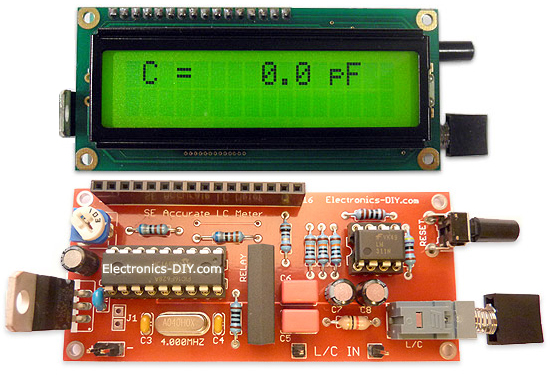
Accurate LC Meter
Build your own Accurate LC Meter (Capacitance Inductance Meter) and start making your own coils and inductors. This LC Meter allows to measure incredibly small inductances making it perfect tool for making all types of RF coils and inductors. LC Meter can measure inductances starting from 10nH - 1000nH, 1uH - 1000uH, 1mH - 100mH and capacitances from 0.1pF up to 900nF. The circuit includes an auto ranging as well as reset switch and produces very accurate and stable readings. |
|
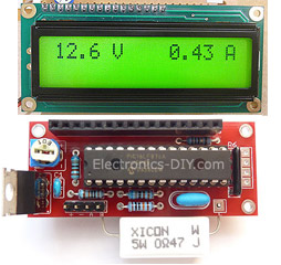
PIC Volt Ampere Meter
Volt Ampere Meter measures voltage of 0-70V or 0-500V with 100mV resolution and current consumption 0-10A or more with 10mA resolution. The meter is a perfect addition to any power supply, battery chargers and other electronic projects where voltage and current must be monitored. The meter uses PIC16F876A microcontroller with 16x2 backlighted LCD. |
|
|
|
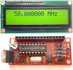
60MHz Frequency Meter / Counter
Frequency Meter / Counter measures frequency from 10Hz to 60MHz with 10Hz resolution. It is a very useful bench test equipment for testing and finding out the frequency of various devices with unknown frequency such as oscillators, radio receivers, transmitters, function generators, crystals, etc. |
|
1Hz - 2MHz XR2206 Function Generator
1Hz - 2MHz XR2206 Function Generator produces high quality sine, square and triangle waveforms of high-stability and accuracy. The output waveforms can be both amplitude and frequency modulated. Output of 1Hz - 2MHz XR2206 Function Generator can be connected directly to 60MHz Counter for setting precise frequency output. |
|
|
|
BA1404 HI-FI Stereo FM Transmitter
Be "On Air" with your own radio station! BA1404 HI-FI Stereo FM Transmitter broadcasts high quality stereo signal in 88MHz - 108MHz FM band. It can be connected to any type of stereo audio source such as iPod, Computer, Laptop, CD Player, Walkman, Television, Satellite Receiver, Tape Deck or other stereo system to transmit stereo sound with excellent clarity throughout your home, office, yard or camp ground. |
|
USB IO Board
USB IO Board is a tiny spectacular little development board / parallel port replacement featuring PIC18F2455/PIC18F2550 microcontroller. USB IO Board is compatible with Windows / Mac OSX / Linux computers. When attached to Windows IO board will show up as RS232 COM port. You can control 16 individual microcontroller I/O pins by sending simple serial commands. USB IO Board is self-powered by USB port and can provide up to 500mA for electronic projects. USB IO Board is breadboard compatible. |
|
|
|
|
ESR Meter / Capacitance / Inductance / Transistor Tester Kit
ESR Meter kit is an amazing multimeter that measures ESR values, capacitance (100pF - 20,000uF), inductance, resistance (0.1 Ohm - 20 MOhm), tests many different types of transistors such as NPN, PNP, FETs, MOSFETs, Thyristors, SCRs, Triacs and many types of diodes. It also analyzes transistor's characteristics such as voltage and gain. It is an irreplaceable tool for troubleshooting and repairing electronic equipment by determining performance and health of electrolytic capacitors. Unlike other ESR Meters that only measure ESR value this one measures capacitor's ESR value as well as its capacitance all at the same time. |
|
Audiophile Headphone Amplifier Kit
Audiophile headphone amplifier kit includes high quality audio grade components such as Burr Brown OPA2134 opamp, ALPS volume control potentiometer, Ti TLE2426 rail splitter, Ultra-Low ESR 220uF/25V Panasonic FM filtering capacitors, High quality WIMA input and decoupling capacitors and Vishay Dale resistors. 8-DIP machined IC socket allows to swap OPA2134 with many other dual opamp chips such as OPA2132, OPA2227, OPA2228, dual OPA132, OPA627, etc. Headphone amplifier is small enough to fit in Altoids tin box, and thanks to low power consumption may be supplied from a single 9V battery. |
|
|
|
|
|
Arduino Prototype Kit
Arduino Prototype is a spectacular development board fully compatible with Arduino Pro. It's breadboard compatible so it can be plugged into a breadboard for quick prototyping, and it has VCC & GND power pins available on both sides of PCB. It's small, power efficient, yet customizable through onboard 2 x 7 perfboard that can be used for connecting various sensors and connectors. Arduino Prototype uses all standard through-hole components for easy construction, two of which are hidden underneath IC socket. Board features 28-PIN DIP IC socket, user replaceable ATmega328 microcontroller flashed with Arduino bootloader, 16MHz crystal resonator and a reset switch. It has 14 digital input/output pins (0-13) of which 6 can be used as PWM outputs and 6 analog inputs (A0-A5). Arduino sketches are uploaded through any USB-Serial adapter connected to 6-PIN ICSP female header. Board is supplied by 2-5V voltage and may be powered by a battery such as Lithium Ion cell, two AA cells, external power supply or USB power adapter. |
|
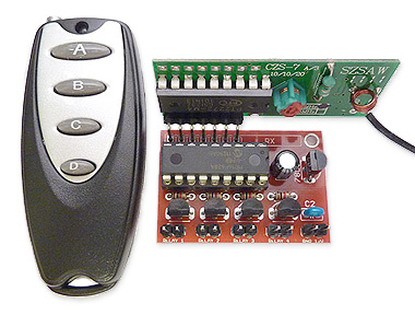
200m 4-Channel 433MHz Wireless RF Remote Control
Having the ability to control various appliances inside or outside of your house wirelessly is a huge convenience, and can make your life much easier and fun. RF remote control provides long range of up to 200m / 650ft and can find many uses for controlling different devices, and it works even through the walls. You can control lights, fans, AC system, computer, printer, amplifier, robots, garage door, security systems, motor-driven curtains, motorized window blinds, door locks, sprinklers, motorized projection screens and anything else you can think of. |
|
|
|