| |
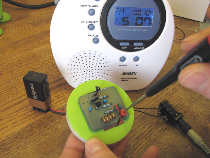
This simple FM Transmitter takes audio input through a 1/4" phono jack and, constructed as shown, without the optional antenna connections, will broadcast an FM radio signal about 30 feet. This is the standard model of simplest FM transmitters includes a trim capacitor to adjust the transmitting frequency. It can be powered by a 9V battery and uses a hand-turned copper coil. The circuit is extraordinarily simple and could be built on perfboard or on a panel almost as easily.
Simplest FM Transmitter Parts
Copper wire (4 inches), enameled, solid, 19 AWG or 20 SWG
1/4" TRS jack, AKA "phono jack" Only tip and shield connections are used.
Battery holder clips, 9V, with 4" leads
PCB, bought or home-etched or use perfboard and jumpers.
Double-sided foam tape (1.5")
Battery, 9V
Mini trim capacitor, 20 pƒ
Ceramic capacitor, 10 pƒ
Ceramic capacitor (2), 0.01 μƒ
NPN silicon transistor, BC337
Electrolytic capacitor, 1 uƒ
Metal film resistor, 470 �Ohm
Metal film resistor, 10 K Ohm
Metal film resistor, 27 K Ohm
Multistrand hookup wire (8"), 24 AWG
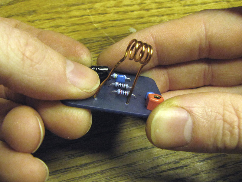
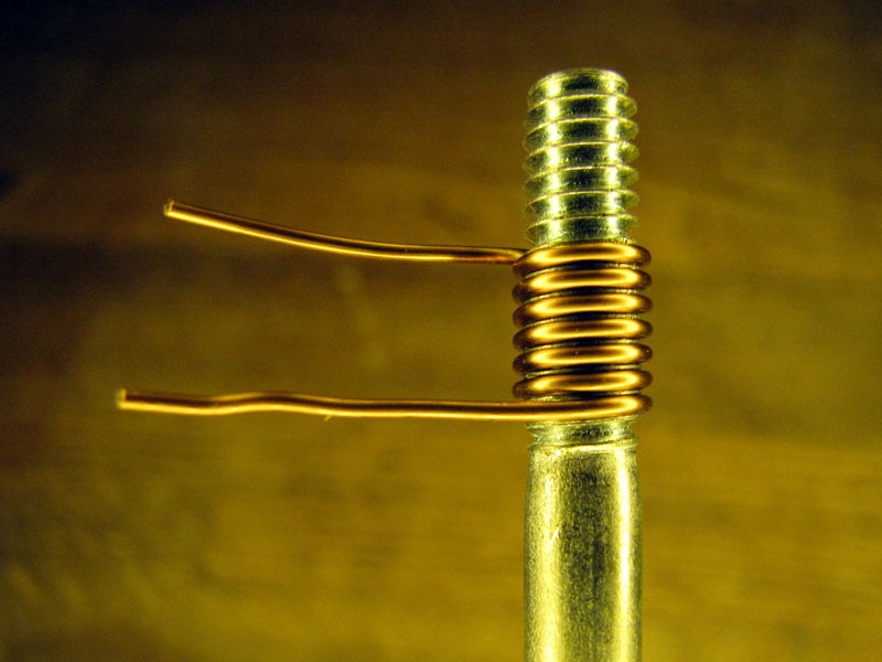
Form coil
Take a piece of 19 AWG enameled copper wire, about 4" long, and wind at least four turns about the threads of a 1/4-20 bolt or machine screw.
Rotate the bolt counterclockwise to unscrew the coil from the thread.
You want a total of four turns in the coil. Use small pliers to bend two legs down, as shown, and side-cutting pliers to clip them to about 1" long.
The mounting holes for the coil legs should be 12mm apart on the surface of the PCB. The act of installing the coil on the board should stretch it to the correct length, but you may have to tweak it a bit with pliers or a screwdriver to make sure the rate of coiling is even between the two legs.
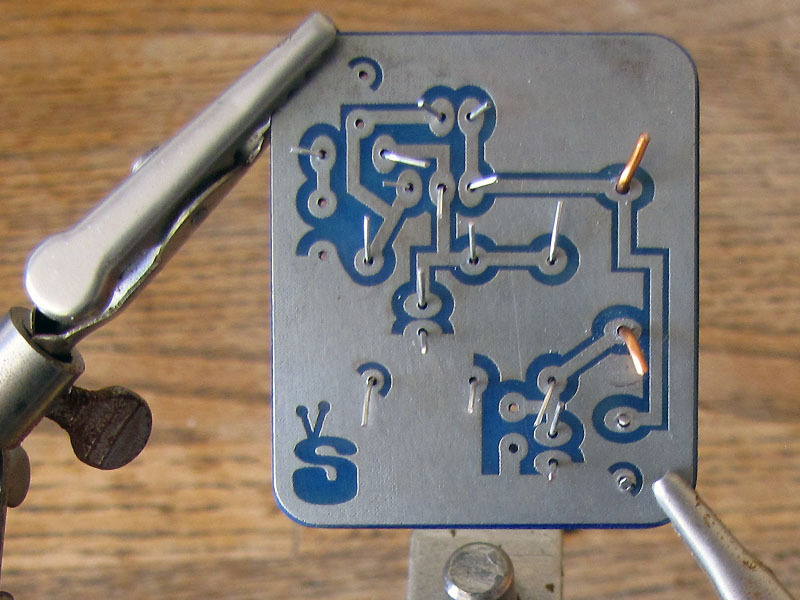
Install components
Bend and slip the component leads into the correct holes in the PCB.
Carefully note and verify the correct orientation of the electrolytic capacitor and wire leads.
Bend the leads on the solder side of the board to temporarily secure the components in place. Clip them to about 1/4" to open up a bit of room to solder in.
Solder components
Clip the PCB, trace-side up, into your helping hands, or otherwise secure it, in a level horizontal orientation.
As always when soldering, be sure to work with plenty of ventilation and avoid inhaling fumes.
Flux, heat, and solder each lead in place.
Once the solder has cooled, clip any protruding leads with side or end-cutting pliers.
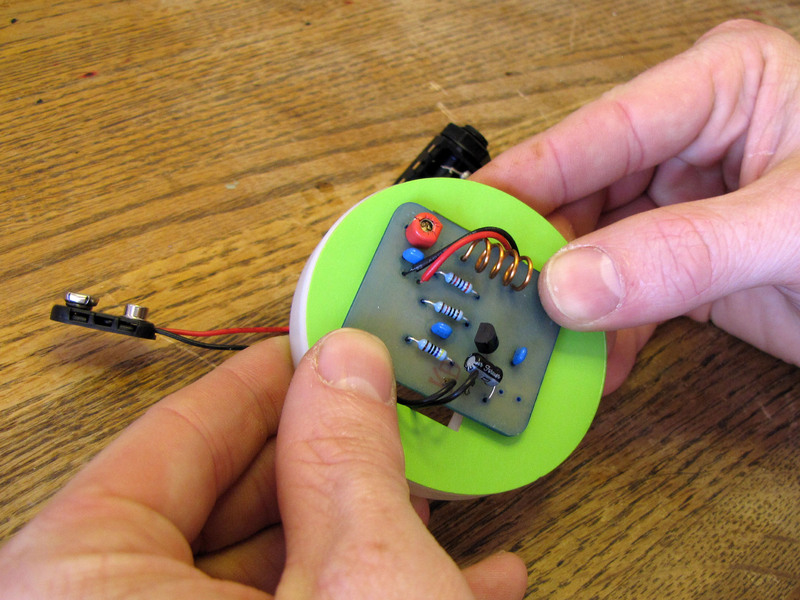
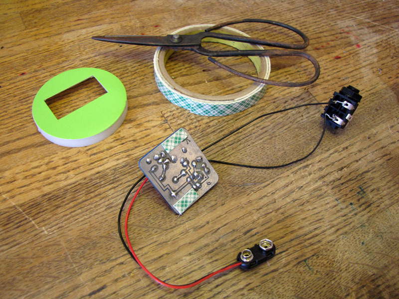
Mount PCB
Mounting details will naturally vary with the case you choose. This foam-tape method worked great for my salvaged clock case, but your mileage may vary.
Attach a strip of double-sided foam tape to the featureless corners of the PCB, on the trace side, as shown. Each strip is about 1/4 x 3/4".
Do not attach tape directly over the traces, or you may damage them if you ever have to remove the tape.
Remove the backing from the foam tape strips on the PCB.
Making sure the leads are first correctly positioned, carefully orient the PCB and press it into place.
Tune circuit
Connect a fresh 9V battery to the battery clip, and an audio signal to the TRS jack. I used the headphone jack of my laptop for an audio source.
Turn on your FM radio, and scan around looking for your signal. I found mine at around 99.8 MHz. It may be quite static-y and noisy at first.
Use a small screwdriver to adjust the trim capacitor, as shown, until your signal comes through loud and clear.
Assemble
Remove the washer and nut from the phono jack and thread it, from inside the case, through the hole you drilled in Step 1.
Put the washer over the threads and tighten the nut down from outside the case, to secure the jack. Finger-tight is fine.
Attach a 9V battery to the clip, pad it with a scrap of bubble wrap, and stuff it in the case before sealing up.
I'm going to to modify my transmitter with a jack for an external regulated power supply. You may want to do the same, or at least add a power switch between the battery and the board. But for testing purposes, this set-up will suffice.
|
|
|
| |
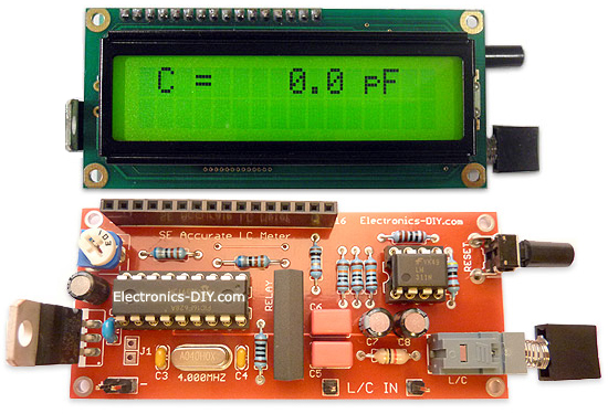
Accurate LC Meter
Build your own Accurate LC Meter (Capacitance Inductance Meter) and start making your own coils and inductors. This LC Meter allows to measure incredibly small inductances making it perfect tool for making all types of RF coils and inductors. LC Meter can measure inductances starting from 10nH - 1000nH, 1uH - 1000uH, 1mH - 100mH and capacitances from 0.1pF up to 900nF. The circuit includes an auto ranging as well as reset switch and produces very accurate and stable readings. |
|
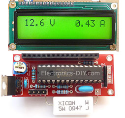
PIC Volt Ampere Meter
Volt Ampere Meter measures voltage of 0-70V or 0-500V with 100mV resolution and current consumption 0-10A or more with 10mA resolution. The meter is a perfect addition to any power supply, battery chargers and other electronic projects where voltage and current must be monitored. The meter uses PIC16F876A microcontroller with 16x2 backlighted LCD. |
|
|
|
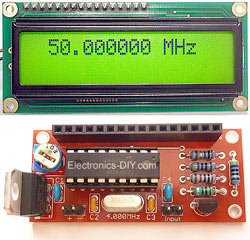
60MHz Frequency Meter / Counter
Frequency Meter / Counter measures frequency from 10Hz to 60MHz with 10Hz resolution. It is a very useful bench test equipment for testing and finding out the frequency of various devices with unknown frequency such as oscillators, radio receivers, transmitters, function generators, crystals, etc. |
|
1Hz - 2MHz XR2206 Function Generator
1Hz - 2MHz XR2206 Function Generator produces high quality sine, square and triangle waveforms of high-stability and accuracy. The output waveforms can be both amplitude and frequency modulated. Output of 1Hz - 2MHz XR2206 Function Generator can be connected directly to 60MHz Counter for setting precise frequency output. |
|
|
|
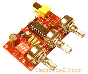
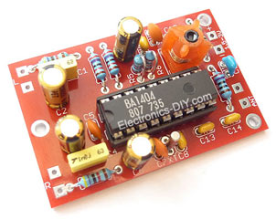
BA1404 HI-FI Stereo FM Transmitter
Be "On Air" with your own radio station! BA1404 HI-FI Stereo FM Transmitter broadcasts high quality stereo signal in 88MHz - 108MHz FM band. It can be connected to any type of stereo audio source such as iPod, Computer, Laptop, CD Player, Walkman, Television, Satellite Receiver, Tape Deck or other stereo system to transmit stereo sound with excellent clarity throughout your home, office, yard or camp ground. |
|
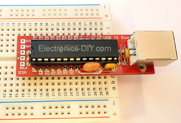
USB IO Board
USB IO Board is a tiny spectacular little development board / parallel port replacement featuring PIC18F2455/PIC18F2550 microcontroller. USB IO Board is compatible with Windows / Mac OSX / Linux computers. When attached to Windows IO board will show up as RS232 COM port. You can control 16 individual microcontroller I/O pins by sending simple serial commands. USB IO Board is self-powered by USB port and can provide up to 500mA for electronic projects. USB IO Board is breadboard compatible. |
|
|
|
|
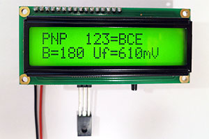
ESR Meter / Capacitance / Inductance / Transistor Tester Kit
ESR Meter kit is an amazing multimeter that measures ESR values, capacitance (100pF - 20,000uF), inductance, resistance (0.1 Ohm - 20 MOhm), tests many different types of transistors such as NPN, PNP, FETs, MOSFETs, Thyristors, SCRs, Triacs and many types of diodes. It also analyzes transistor's characteristics such as voltage and gain. It is an irreplaceable tool for troubleshooting and repairing electronic equipment by determining performance and health of electrolytic capacitors. Unlike other ESR Meters that only measure ESR value this one measures capacitor's ESR value as well as its capacitance all at the same time. |
|
Audiophile Headphone Amplifier Kit
Audiophile headphone amplifier kit includes high quality audio grade components such as Burr Brown OPA2134 opamp, ALPS volume control potentiometer, Ti TLE2426 rail splitter, Ultra-Low ESR 220uF/25V Panasonic FM filtering capacitors, High quality WIMA input and decoupling capacitors and Vishay Dale resistors. 8-DIP machined IC socket allows to swap OPA2134 with many other dual opamp chips such as OPA2132, OPA2227, OPA2228, dual OPA132, OPA627, etc. Headphone amplifier is small enough to fit in Altoids tin box, and thanks to low power consumption may be supplied from a single 9V battery. |
|
|
|
|
|
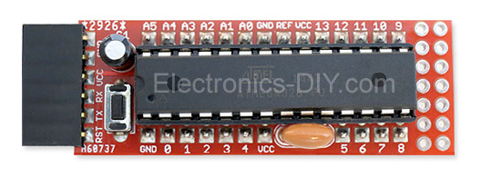
Arduino Prototype Kit
Arduino Prototype is a spectacular development board fully compatible with Arduino Pro. It's breadboard compatible so it can be plugged into a breadboard for quick prototyping, and it has VCC & GND power pins available on both sides of PCB. It's small, power efficient, yet customizable through onboard 2 x 7 perfboard that can be used for connecting various sensors and connectors. Arduino Prototype uses all standard through-hole components for easy construction, two of which are hidden underneath IC socket. Board features 28-PIN DIP IC socket, user replaceable ATmega328 microcontroller flashed with Arduino bootloader, 16MHz crystal resonator and a reset switch. It has 14 digital input/output pins (0-13) of which 6 can be used as PWM outputs and 6 analog inputs (A0-A5). Arduino sketches are uploaded through any USB-Serial adapter connected to 6-PIN ICSP female header. Board is supplied by 2-5V voltage and may be powered by a battery such as Lithium Ion cell, two AA cells, external power supply or USB power adapter. |
|
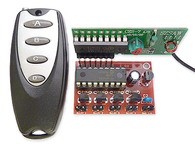
200m 4-Channel 433MHz Wireless RF Remote Control
Having the ability to control various appliances inside or outside of your house wirelessly is a huge convenience, and can make your life much easier and fun. RF remote control provides long range of up to 200m / 650ft and can find many uses for controlling different devices, and it works even through the walls. You can control lights, fans, AC system, computer, printer, amplifier, robots, garage door, security systems, motor-driven curtains, motorized window blinds, door locks, sprinklers, motorized projection screens and anything else you can think of. |
|
|
|