| |
A Wide Dynamic Range Field Strength Meter |
|
This unit is an updated version of the Wide Dynamic Range Field Strength Meter. While the basic function is the same, it has several critical differences:
It uses a specialized integrated circuit, the Analog Devices AD8307. This chip is designed specifically as a logarithmic amplifier for use through 500 MHz.
Using the AD8307, it has a wider dynamic range (85 dB versus 55 dB) and it has built-in temperature compensation.
Because of the different nature of this type of detector - and the fact that it has temperature compensation - means that there is no need for a "zeroing" control.
One disadvantage of this approach as compared to the diode approach is that the AD8307 has a lower frequency response than the diode. The frequency limit of the meter is dictated pretty much by the diodes themselves along with their physical layout and related components: There is no reason why the earlier version could not be constructed to work through 10 GHz or so - but the AD8307 is falling flat by the time you get to 1 GHz, making it unsuitable for detecting wireless LANs or PCS-type cell phones.

Make sure you also read the "Narrowband Field Strength Meter System" page as well.
For more information on field strength meters and how they work, see the discussion of Field Strength Meters, on the "Field Strength Meter" page.
Circuit description:
Inside the field strength meter, showing the placement of the circuit board, battery, piezoelectric speaker, RF connector, and switches.
The 20 dB attenuator:
A useful addition to this meter is that of a switchable 20 dB attenuator. When getting very close to the transmitter - particularly if it's a fairly powerful one - the signal may constantly "peg" the meter. Being able to throw in a bit of extra attenuation allows one to be able to knock the signal down to something other than full-scale. Additionally, if you are getting very near a high-powered transmitter, there is the possibility that the detector may damaged if you accidentally get the transmitting and receiving antennas too close to each other.
This attenuator is built around S1, a subminiature DPDT slide switch. Note that the "ideal" resistor values are closer to 62 ohms and 240 ohms than the more standard 68 ohms and 270 ohms, respectively, but the values shown are more likely to be found in one's resistor drawer and represent about 1 dB of difference from ideal.
It is important to note that a simple attenuator such as this, built onto a subminiature slide switch, will start to degrade badly above 500 MHz. On the unit that I built, I observed a consistent 21 dB of attenuation from 1 MHz through 2 meters, dropping to 18 dB at 70 cm and going down to about 11 dB at 1 GHz. This is due to the inductance/capacitance of the resistors being used as well as cross-coupling between sections of the switch.
The logarithmic amplifier/detector:
The heart of this meter is U1, an Analog Devices AD8307 logarithmic amplifier. This IC contains numerous cascaded RF amplifiers, each connected to a detector output. The weaker signals are amplified by all of these amplifiers in series and by the time the signal gets to the last one in the chain, it has been amplified considerably and can be detected. As the signal gets stronger, the amplifiers farther down the chain start to get saturated and can no longer provide any more output - but the "earlier" amplifiers have not yet saturated and continue to contribute to the output.
In this manner, a very wide range of signals can be detected, with good accuracy, and with a single IC. Inside U1 is a fairly sophisticated compensation network that provides good temperature compensation and stabilization. With this internal circuitry, the output of the log amp stays within 1 dB over a very wide temperature range and a "zeroing" control is not even required.
A close-up of the top of the unit showing the input connector and switchable 20 dB attenuator .
Meter drive circuit:
The output of U1 is a voltage (derived from a current source and a resistor) that is buffered by U2A and then sent, via scaling resistors R5 (and R10) to the meter, M1. Only one half of U2 is used, but the other half could be used if, for instance you wished to provide additional offset, scaling or even drive to an external device.
The audible indicator:
A useful addition to this device is an audible indicator. When I am using the field strength meter, I find myself listening to the tone much more than looking at the meter, as one can walk and look around for the signal source without having to glance continually at the meter face. Personally, I would not want to use a meter without one.
The VCO (Voltage Controlled Oscillator) portion of U3 is used to provide a tone pitch that is proportional to the strength of the detected signal. The voltage from the output of U2 is rescaled using resistors R6, R7, and R8 to a frequency range that is comfortably reproduced by the piezoelectric speaker, SPK1.
Note that it is necessary to use R6-R8 for scaling or else the range of frequencies would range from too low to be useful (e.g. clicking from the speaker) to tones high enough to bother dogs. This resistor arrangement "centers" the voltage in a range that is more-or-less in the middle of the high speech range. You may wish to vary R6-R8 slightly to suit your tastes and to accommodate variations in U3 and C7.
If you have never used a piezoelectric speaker before, it may seem to you to behave oddly. Unlike "normal" speakers (e.g. those with magnets, cones, etc.) these respond best to mid-high audio frequencies. Not only that, to maximize efficiency, they have a chamber and a hole to be broadly resonant in their intended frequency range. Because the drive signal from U3 is a square wave, it is extremely rich in harmonics and because of this one may hear predominantly harmonics when the frequency is lower (e.g. lower signal levels.) In practice, this isn't a problem as most people can distinguish the pitch changes anyway. If you choose to use a more conventional speaker, note that U3 cannot drive it directly and a simple circuit will be needed to provide good output. This drive circuit could be as complex as an audio amplifier (perhaps based on an LM386) or it might be as simple as an emitter follower and resistor.
Note that no "on/off" switch is shown for the audible tone generator. This circuit draws less than 1 mA from the battery - a fraction of the total. If you need to silence the tone, simply covering the speaker's hole with a finger will work, but it would be very easy to add a simple on/off switch.
Constructing the unit:
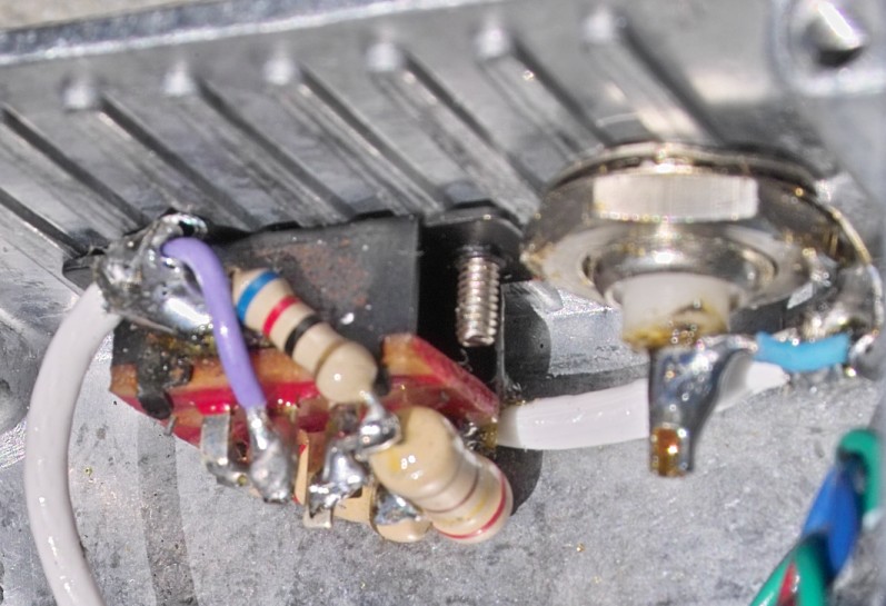
Figure 4: A close-up of the back side of the switchable 20 dB attenuator and input connector.
The schematic is shown in the upper portion of page.
It is strongly recommended that this meter be housed in a shielded (metal) enclosure to assure that any signals registering on the meter are those that are entering via the antenna connector.
As can be seen from the pictures, all circuits were constructed on phenolic "perfboard" and the ICs were socketed. While the use of perfboard and IC sockets can contribute to degraded accuracy at higher frequencies (see the commends in "Using the unit" below) absolute accuracy was not considered to be of extreme priority as this instrument was designed simply for the detection of RF.
Nevertheless, there are a few building techniques that can greatly enhance the accuracy when using perfboard techniques at UHF:
Use a layout that promotes as short interconnections as possible. For the RF inputs, it just makes sense to place the input blocking capacitors and terminating resistor (C1, C2, and R4) as close to the IC as possible.
Use physically small components. Don't use very large ceramic capacitors for C1 and C2, for example, but use the smaller, low-voltage types.
Use a low-profile IC socket. These are the most common types found these days.
Use a heavy, short ground bus for the DC/RF return between the RF input and the IC's ground pins, as noted in the picture and on the schematic.
Keeping these in mind, connections were quite short and laid out close to the IC. Once you "get past" the RF portions, however, layout is no longer as critical and conventional audio/HF layout techniques may be used.
Clearly, if you wanted to obtain performance that was as close to the intrinsic accuracy of the chip, the best course of action would be to lay out a proper double-sided circuit board (with through-holes and vias) and use exclusively surface-mount components. On the unit that I built, I happened to solder a surface-mount capacitor on the bottom of the IC socket, but this may be overkill (and I had the capacitor, anyway...)
The connection from the RF input was simply via a BNC connector and short lengths of miniature coaxial cable. These short lengths of cable connect not only the input connector to the attenuator, but from the attenuator to the circuit board as well.
When mounting the piezoelectric speaker, make sure that the hole in the enclosure is at list half again as large as the hold in the piezo speaker itself. If they are the same size - or if the hole in the enclosure is smaller than the one on the speaker - efficiency may suffer greatly due to the broad, self-resonance of the piezo being dampened. Note that an on/off switch was not provided for the sounder/speaker. If this is desired, one may use the switch to either interrupt the output from pin 4 of U3, or simply have it remove the power from U3, pin 16 and save a milliamp or so.
Constructing the 20 dB switchable attenuator:
The use of short leads is a must for best performance of the attenuator. As can be seen from figure 4, the "ground" of the resistors and the coax was soldered directly to the body of the attenuator switch which, in turn, is fastened to the shielded enclosure. Soldering to the switch can, however, present a problem: It is steel, and electrical solder does not adhere well to steel using standard rosin flux.
To get a good connection to the body of the switch, one needs a hot iron to allow connections to be made quickly and avoid melting the plastic components of the switch. In addition, one needs to scrape the metal clean with sandpaper or a knife, removing any paint, lacquer, and/or oxide coating at those areas where a connection will be made. Finally, to make a reliable solder connection, a flux more aggressive than that found in electrical solder must be used. The preferred flux is a strong acid flux used for soldering to stainless steel, but it turns out that the paste flux used for plumbing will also work.
When done soldering to the steel switch body, verify mechanically and electrically (with an ohmmeter) that you haven't overheated the switch and melted the plastic components within and that the switch operates properly. At this point, it is a good idea to remove any remaining flux to prevent chemical corrosion and for this task I typically use cotton swabs and denatured alcohol.
The log amp (main board) and the audible tone generator (the board at the right-angle.) The bottom of the main board. The RF input is on the right.
The majority of the parts are commonly available. The AD8307AN may be obtained from Digi-Key electronics. Make certain that you get the DIP version of AD8307AN - unless you plan to build a version with surface-mount parts. The LMC6482IN dual op-amp. Again, make sure that you get the DIP version. A MAX492 may be substituted for the LMC6482IN but note that the MAX492 has a maximum limitation of 7 volts. This isn't a problem, but it means that the "V+" connected to pin 8 of U2 must be connected to the +5 volt output from the voltage regulator. (Once again, make certain that you get the DIP version - unless you plan to build a version with surface-mount parts.) The meter shown is a 1 mA meter movement. This is disguised as a 15 volt DC meter (supplied with a scaling resistor). Other meter movements may be used, provided that R10 is recalculated to limit the maximum current to the meter to a safe value should R5 be "turned up" all of the way. The piezoelectric sounder is a 2-lead type (without internal drive circuitry). Switches S1 and S2 (power and attenuator) are from a "6 piece slide switch kit".
Mounting components:
The most time-consuming portions of construction involve putting the project into its case. The specified meter comes with a hole template: One needs to make sure that the corners of the meter do not interfere with the screws used to hold the case together.
The holes for the meter and slide switches were creating using the "drill 'n file" method in which smaller holes are drilled corresponding with the component being mounted and then enlarged (by breaking/cutting pieces of the enclosure "between" holds) and squared or sized up using a set of needle files (available at many hardware stores or even Radio Shack.) After the larger holes have been sized properly for the meter and switches, additional holes are drilled for the mounting screws.
Calibrating the unit:
If you have test equipment:
If you have test equipment, calibration is very straightforward: Using a frequency generator anywhere from 1 MHz to 200 Mhz, feed a +10 dBm signal into the input and set the "full scale" pot (R5) for a full-scale reading! One would then adjust the signal generator 10 dB at a time, noting each one on the scale. (You would, of course, have the 20 dB attenuator switched out...)
If you don't have access to a signal generator that is capable of at least +10 dBm, you can extrapolate the reading as follows:
Set the output of the signal generator to, say, -60 dBm and note the reading.
Set the output of the signal generator to -50 dBm and note the difference in the reading. Do the same at -40 dBm.
Taking the differences between the readings you can determine the average size of 10 dB steps and extrapolate where a reading of +10 dBm would be and adjust R5.
If you don't have any test equipment:
If you don't have any test equipment handy, the goal is to make as much of the range of the instrument as possible appear on the meter:
Start off with R5 set only about 1/4 of the way up from the "ground" end and make sure that the 20 dB attenuator is switched out.
Using a 2 meter HT, set it to low power (or anything from 0.1 to 0.5 watts) and, with a rubber duck antenna connected to the field strength meter, key it up within a foot or so of the meter and move it around a bit. Get a "feel" of what the "maximum" reading will be, adjusting R5 downward if the meter pegs.
Adjust R5 so that the "maximum" signal just barely pegs the meter.
You are done!
While this second method isn't scientific, but it will guarantee that you'll get the full range from the field strength meter. See the schematic of Wide Dynamic range field strength meter.
Using the unit:
When first switching on the unit, always disconnect the antenna and note where the minimum reading will be. This meter does not have a "zeroing" control but you'll also notice that even with no signal applied, it will still read upscale from zero a bit. This reading is largely due to the intrinsic noise of the input detector stages (e.g. thermal "background noise") of the chip and is not a malfunction. Because the meter reads in decibels, you cannot possibly ever get to "zero" (no signal) anyway, so once has to decide, at some point, what the "minimum reading" can be. In this case, the sensitivity of the AD8307 itself is the limiting factor and this is typically around -75 dBm, varying slightly with temperature and from unit-to-unit.
With a small rubber duck (or any antenna) connected, you'll likely observe a signal strength reading even if you don't happen to have a signal generator or transmitter nearby. Depending on your precise location, you will likely be detecting any nearby broadcast radio/TV stations (or other transmitters - including your own!) Note that because this meter is completely untuned, what you are detecting could be anywhere in the range of AM broadcast through cellular telephone frequencies. It is worth mentioning that, for this reason, you should not be talking on an HT (or even a cell phone) while using it!
In metro areas, you may find that you will get a reading from distant transmitters - even if the 20 dB attenuator is switched in! Keep in mind that the signals being received may be anything from AM broadcast band through UHF TV stations that your antenna just happens to be able to pick up. In such a metro area, it may be worth building a bandpass filter, tuned to pass only those frequencies (near) those of interest. If there is enough room, a set of such filters may be built into the unit - or they may be outboard modules connected between the field strength meter and the antenna lead.
If you get close enough to the transmitter that the signal is consistently above half-scale to two-thirds scale, it may be time to switch in the attenuator. Experience has shown that, with the attenuator switched in, a nearly full-scale reading indicates that you are probably within an arm's length of the object of your search. In a test, the meter was connected to a 1/4 wave magnetic-mount antenna near the rear of the car roof and a 50 watt 2 meter signal was transmitted into a 5/8 wave mag-mount antenna at the front of the car roof (about 8 feet apart.) With the 20 dB attenuator switched in, the meter was "almost" pegged.
When using this (or any) field strength meter, you may want to have a choice of two different antennas:
A directive array. This could be a small yagi or quad, or it could even be a simple shielded loop antenna. A gain antenna will allow detection of a transmitter at a greater distance and can provide a directional indication of the transmitter's location, but it can be somewhat large and conspicuous. A shielded loop can offer directivity, but its best attribute is its deep null, and it takes practice to effectively use it.
An omnidirectional antenna. This would probably take the form of a simple rubber-duck antenna. This is smaller and less conspicuous than a directional antenna but is less-sensitive. While it does not have any predictable directional characteristics, one can use the "body-shield" method to ascertain the general bearing of the transmitter.
The AD8307 has built-in temperature compensation so that over the expected temperature range (freezing to hot) it will be stable to be within 1 dB. Accuracy over the entire frequency range will likely be somewhat worse than this, owing to a few factors:
The frequency response of the AD8307 itself. This will be down by a dB or so by the time you get to 500 MHz.
Losses/mismatch in the circuit layout. When you get up to several hundred MHz, it takes very careful layout and selection of components to avoid stray losses. The AD8307 is good enough that these losses start to come into play. Using perfboard, as shown in the prototype, it is very difficult to provide a low-loss layout, but careful attention to detail can minimize these.
The input attenuator circuit. The prototype uses a 20 dB switchable attenuator using a standard subminiature slide switch and resistors. These components were not designed for optimum performance at frequencies of several hundred MHz and the performance of this attenuator will suffer in terms of added losses (on the "zero" attenuation setting) as well as cross-coupling through the switch (when in the 20 dB setting) which will reduce the attenuation from 20 dB to something lower, typically in the 15-18 dB area, depending on exact component layout.
Maximum input signal level and the response above 300 MHz:
The AD8307 is rated to respond properly to signal levels up to +17 dBm (50 milliwatts) input: Higher than this exceeds the recommended rating of the chip and could cause damage. Above 200-300 MHz or so this chip will start to compress at +10 dBm and by the time you get to 500 MHz, however, the AD8307 will start to "compress" above about +5 dBm. While no damage will be done, this is worth noting so that one can know to switch in the 20 dB attenuator.
Detecting cell phones and wireless LANs:
The AD8307 used in this device starts to lose sensitivity above about 500 MHz and is down several dB by the time one gets to the Cell Phone band (below 900 MHz) and the sensitivity drops like a rock above 1 GHz. For this reason, it will not easily detect PCS-type phones or wireless LANs as well as the Mark I version can.
Note also that digital cell phones and wireless LANs often have very short duty cycle transmissions: This circuit does not have any sort of "peak/hold" detector and very brief transmissions may not be noticed.
Additional comments:
The use of the AD8307 in ham radio project is, by no means, unique and is used from field strength meters to power meters. This project was designed to be about as simple and usable as practical, while retaining the benefits of this device.


|
|
|
| |
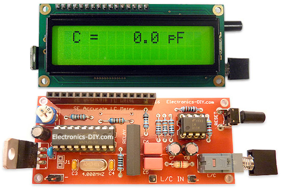
Accurate LC Meter
Build your own Accurate LC Meter (Capacitance Inductance Meter) and start making your own coils and inductors. This LC Meter allows to measure incredibly small inductances making it perfect tool for making all types of RF coils and inductors. LC Meter can measure inductances starting from 10nH - 1000nH, 1uH - 1000uH, 1mH - 100mH and capacitances from 0.1pF up to 900nF. The circuit includes an auto ranging as well as reset switch and produces very accurate and stable readings. |
|
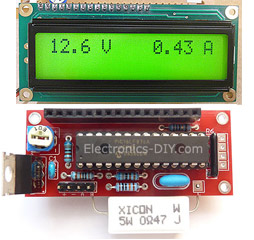
PIC Volt Ampere Meter
Volt Ampere Meter measures voltage of 0-70V or 0-500V with 100mV resolution and current consumption 0-10A or more with 10mA resolution. The meter is a perfect addition to any power supply, battery chargers and other electronic projects where voltage and current must be monitored. The meter uses PIC16F876A microcontroller with 16x2 backlighted LCD. |
|
|
|
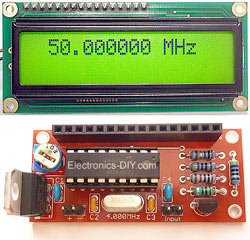
60MHz Frequency Meter / Counter
Frequency Meter / Counter measures frequency from 10Hz to 60MHz with 10Hz resolution. It is a very useful bench test equipment for testing and finding out the frequency of various devices with unknown frequency such as oscillators, radio receivers, transmitters, function generators, crystals, etc. |
|
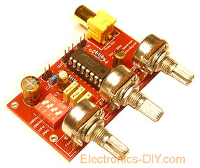
1Hz - 2MHz XR2206 Function Generator
1Hz - 2MHz XR2206 Function Generator produces high quality sine, square and triangle waveforms of high-stability and accuracy. The output waveforms can be both amplitude and frequency modulated. Output of 1Hz - 2MHz XR2206 Function Generator can be connected directly to 60MHz Counter for setting precise frequency output. |
|
|
|
BA1404 HI-FI Stereo FM Transmitter
Be "On Air" with your own radio station! BA1404 HI-FI Stereo FM Transmitter broadcasts high quality stereo signal in 88MHz - 108MHz FM band. It can be connected to any type of stereo audio source such as iPod, Computer, Laptop, CD Player, Walkman, Television, Satellite Receiver, Tape Deck or other stereo system to transmit stereo sound with excellent clarity throughout your home, office, yard or camp ground. |
|
USB IO Board
USB IO Board is a tiny spectacular little development board / parallel port replacement featuring PIC18F2455/PIC18F2550 microcontroller. USB IO Board is compatible with Windows / Mac OSX / Linux computers. When attached to Windows IO board will show up as RS232 COM port. You can control 16 individual microcontroller I/O pins by sending simple serial commands. USB IO Board is self-powered by USB port and can provide up to 500mA for electronic projects. USB IO Board is breadboard compatible. |
|
|
|
|
ESR Meter / Capacitance / Inductance / Transistor Tester Kit
ESR Meter kit is an amazing multimeter that measures ESR values, capacitance (100pF - 20,000uF), inductance, resistance (0.1 Ohm - 20 MOhm), tests many different types of transistors such as NPN, PNP, FETs, MOSFETs, Thyristors, SCRs, Triacs and many types of diodes. It also analyzes transistor's characteristics such as voltage and gain. It is an irreplaceable tool for troubleshooting and repairing electronic equipment by determining performance and health of electrolytic capacitors. Unlike other ESR Meters that only measure ESR value this one measures capacitor's ESR value as well as its capacitance all at the same time. |
|
Audiophile Headphone Amplifier Kit
Audiophile headphone amplifier kit includes high quality audio grade components such as Burr Brown OPA2134 opamp, ALPS volume control potentiometer, Ti TLE2426 rail splitter, Ultra-Low ESR 220uF/25V Panasonic FM filtering capacitors, High quality WIMA input and decoupling capacitors and Vishay Dale resistors. 8-DIP machined IC socket allows to swap OPA2134 with many other dual opamp chips such as OPA2132, OPA2227, OPA2228, dual OPA132, OPA627, etc. Headphone amplifier is small enough to fit in Altoids tin box, and thanks to low power consumption may be supplied from a single 9V battery. |
|
|
|
|
|
Arduino Prototype Kit
Arduino Prototype is a spectacular development board fully compatible with Arduino Pro. It's breadboard compatible so it can be plugged into a breadboard for quick prototyping, and it has VCC & GND power pins available on both sides of PCB. It's small, power efficient, yet customizable through onboard 2 x 7 perfboard that can be used for connecting various sensors and connectors. Arduino Prototype uses all standard through-hole components for easy construction, two of which are hidden underneath IC socket. Board features 28-PIN DIP IC socket, user replaceable ATmega328 microcontroller flashed with Arduino bootloader, 16MHz crystal resonator and a reset switch. It has 14 digital input/output pins (0-13) of which 6 can be used as PWM outputs and 6 analog inputs (A0-A5). Arduino sketches are uploaded through any USB-Serial adapter connected to 6-PIN ICSP female header. Board is supplied by 2-5V voltage and may be powered by a battery such as Lithium Ion cell, two AA cells, external power supply or USB power adapter. |
|
200m 4-Channel 433MHz Wireless RF Remote Control
Having the ability to control various appliances inside or outside of your house wirelessly is a huge convenience, and can make your life much easier and fun. RF remote control provides long range of up to 200m / 650ft and can find many uses for controlling different devices, and it works even through the walls. You can control lights, fans, AC system, computer, printer, amplifier, robots, garage door, security systems, motor-driven curtains, motorized window blinds, door locks, sprinklers, motorized projection screens and anything else you can think of. |
|
|
|