| |
Oscilloscope Probe Schematic & Anatomy |
|
Passive Probe are the most general used scope probe. As the name "passive" suggest, it is made from passive components resistor, capacitor & wires. The leading scope probe maker are LeCroy, Tektronix & Agilent.
Passive probe usually comes with attenuation factor of 1:1, 10:1 and 100:1. Attenuation factor of 1:1 means whatever signal being probe at the probe tip will be shown exactly as it is at the oscilloscope input. So a signal of 1V at the probe tip will be detected as 1V at the scope input.
Attenuation factor of 10:1 means that a signal of 1V at probe tip will be detected as 0.1V at the scope input.
Why do we want to use a scope probe of attenuation 10:1 ? The reason is that it has ten time capacitance smaller at the probe tip as well. A typical 10:1 scope probe will have about 9pF to 15pF at the probe tip compare to 50pF to 100pF for a 1:1 scope probe. The smaller the probe tip capacitance, the better it is for high frequency signal measurement. For a 10:1 scope probe, it could measure signal up to 500MHz whereas for a 1:1 scope probe, it could only measure signal up to 15~20MHz.
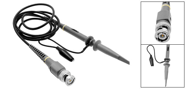
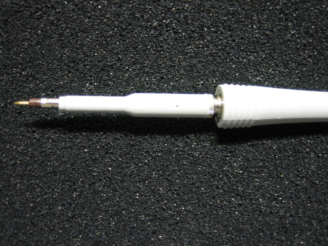
We will go through the details of the oscilloscope probe anatomy and schematic now. The figure below show a full view of a scope probe available in the market. This scope probe has 10:1 attenuation, 10M ohm input resistance with 10pF input capacitance.
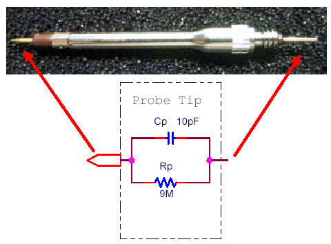
Measure the probe tip resistance & capacitance. The equivalent probe tip schematic is shown below. From here we know that the probe tip resistance is 9Mohm and the probe tip capacitance is 10pF in parallel with the 9Mohm resistor.
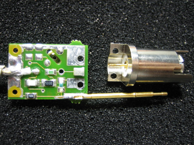
Next, we move on to dismantle the probe connector. After removing the plastic casing, there is a small PCB with a metal shield.
Remove the metal shield and we could see the passive components now. There are a couple of SMT resistors and capacitors mounted on the PCB.
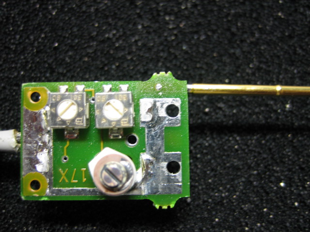
Then we look at the opposite side of the PCB. There are two variable resistors and one variable capacitor on this side of PCB. The two variable resistors are used for high frequency compensation and the variable capacitor is use for low frequency compensation. We will show how these variable components works later.
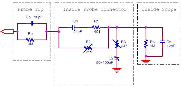
From here we could derive the probe compensation schematic inside the probe connector. Click the image below to view in enlarge format.
From the schematic above, we have shown the probe tip, probe connector and oscilloscope circuit diagram. The typical oscilloscope input resistance is 1M ohm with a 12pF capacitance in parallel. We must include these resistor and capacitor into the calculation in order to obtain the correct compensation network calculation. R2 & R3 are the variable resistors (range of 0 to 500 Ohm) and C2 is the variable capacitor (Range of 50pF to 100pF).
We could simplify the schematic above into the circuit as shown below. Our objective is to calculate the relationship between Vin and Vscope across frequency from 100Hz to 100MHz.
Z1 is the impedance of Cp and Rp in parallel. [ Z1= Rp // (1/sCp) ]
Z3 is the impedance of (C1 & R1 in series) and parallel with R2. [ Z3= (R1+ (1/sC1)) // R2 ]
Z4 is the impedance of C2 and R3 in series. [ Z4 = R3 + (1/sC2) ]
Z6 is the impedance of Rs and Cs in parallel. [ Z6 = Rs // (1 /sCs) ]
The table below shows the calculation of Vout versus Vin of 1V. As we can see, from 1Hz to 100kHz, the attenuation is 10 times. (Vout =1V /10=0.1V ). From 1M to 100M, the attenuation become lesser due to Z1 reduce steeply from 115k Ohm to less than 1k Ohm. This is the result of impedance Xcp has reduced as the frequency increase Xcp = 1/sCp ( s = 2*pi*freq).
We can say that with the passive components value as shown above, the scope probe has an accurate 10:1 attenuation from 1 Hz to 100kHz. From 1 MHz onwards, we need to fine tune the variable resistor R3 in order to obtain the 10:1 attenuation. Let change the R3 from 147 ohm to 50 ohm and check out the VOUT value now. It is clear that VOUT is almost consistently 0.1 across all the frequency from 1Hz to high freq 100MHz.
Conclusion:
1) Scope probe has compensation network to fine tune the VOUT value close to the attenuation value 10:1.
2) During the calculation of scope probe VOUT, we need to include the input resistor and capacitance of oscilloscope as well.
|
|
|
| |
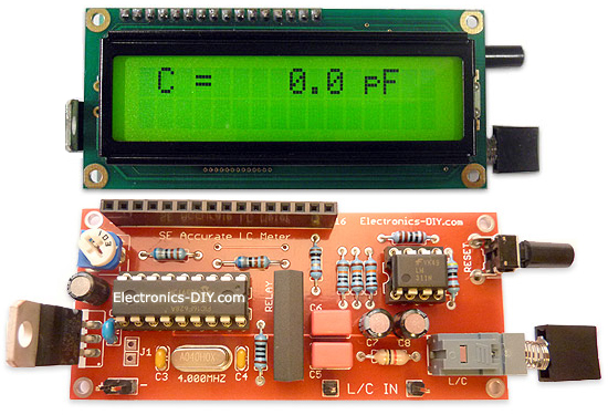
Accurate LC Meter
Build your own Accurate LC Meter (Capacitance Inductance Meter) and start making your own coils and inductors. This LC Meter allows to measure incredibly small inductances making it perfect tool for making all types of RF coils and inductors. LC Meter can measure inductances starting from 10nH - 1000nH, 1uH - 1000uH, 1mH - 100mH and capacitances from 0.1pF up to 900nF. The circuit includes an auto ranging as well as reset switch and produces very accurate and stable readings. |
|
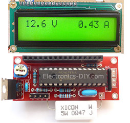
PIC Volt Ampere Meter
Volt Ampere Meter measures voltage of 0-70V or 0-500V with 100mV resolution and current consumption 0-10A or more with 10mA resolution. The meter is a perfect addition to any power supply, battery chargers and other electronic projects where voltage and current must be monitored. The meter uses PIC16F876A microcontroller with 16x2 backlighted LCD. |
|
|
|
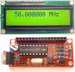
60MHz Frequency Meter / Counter
Frequency Meter / Counter measures frequency from 10Hz to 60MHz with 10Hz resolution. It is a very useful bench test equipment for testing and finding out the frequency of various devices with unknown frequency such as oscillators, radio receivers, transmitters, function generators, crystals, etc. |
|
1Hz - 2MHz XR2206 Function Generator
1Hz - 2MHz XR2206 Function Generator produces high quality sine, square and triangle waveforms of high-stability and accuracy. The output waveforms can be both amplitude and frequency modulated. Output of 1Hz - 2MHz XR2206 Function Generator can be connected directly to 60MHz Counter for setting precise frequency output. |
|
|
|
BA1404 HI-FI Stereo FM Transmitter
Be "On Air" with your own radio station! BA1404 HI-FI Stereo FM Transmitter broadcasts high quality stereo signal in 88MHz - 108MHz FM band. It can be connected to any type of stereo audio source such as iPod, Computer, Laptop, CD Player, Walkman, Television, Satellite Receiver, Tape Deck or other stereo system to transmit stereo sound with excellent clarity throughout your home, office, yard or camp ground. |
|
USB IO Board
USB IO Board is a tiny spectacular little development board / parallel port replacement featuring PIC18F2455/PIC18F2550 microcontroller. USB IO Board is compatible with Windows / Mac OSX / Linux computers. When attached to Windows IO board will show up as RS232 COM port. You can control 16 individual microcontroller I/O pins by sending simple serial commands. USB IO Board is self-powered by USB port and can provide up to 500mA for electronic projects. USB IO Board is breadboard compatible. |
|
|
|
|
ESR Meter / Capacitance / Inductance / Transistor Tester Kit
ESR Meter kit is an amazing multimeter that measures ESR values, capacitance (100pF - 20,000uF), inductance, resistance (0.1 Ohm - 20 MOhm), tests many different types of transistors such as NPN, PNP, FETs, MOSFETs, Thyristors, SCRs, Triacs and many types of diodes. It also analyzes transistor's characteristics such as voltage and gain. It is an irreplaceable tool for troubleshooting and repairing electronic equipment by determining performance and health of electrolytic capacitors. Unlike other ESR Meters that only measure ESR value this one measures capacitor's ESR value as well as its capacitance all at the same time. |
|
Audiophile Headphone Amplifier Kit
Audiophile headphone amplifier kit includes high quality audio grade components such as Burr Brown OPA2134 opamp, ALPS volume control potentiometer, Ti TLE2426 rail splitter, Ultra-Low ESR 220uF/25V Panasonic FM filtering capacitors, High quality WIMA input and decoupling capacitors and Vishay Dale resistors. 8-DIP machined IC socket allows to swap OPA2134 with many other dual opamp chips such as OPA2132, OPA2227, OPA2228, dual OPA132, OPA627, etc. Headphone amplifier is small enough to fit in Altoids tin box, and thanks to low power consumption may be supplied from a single 9V battery. |
|
|
|
|
|
Arduino Prototype Kit
Arduino Prototype is a spectacular development board fully compatible with Arduino Pro. It's breadboard compatible so it can be plugged into a breadboard for quick prototyping, and it has VCC & GND power pins available on both sides of PCB. It's small, power efficient, yet customizable through onboard 2 x 7 perfboard that can be used for connecting various sensors and connectors. Arduino Prototype uses all standard through-hole components for easy construction, two of which are hidden underneath IC socket. Board features 28-PIN DIP IC socket, user replaceable ATmega328 microcontroller flashed with Arduino bootloader, 16MHz crystal resonator and a reset switch. It has 14 digital input/output pins (0-13) of which 6 can be used as PWM outputs and 6 analog inputs (A0-A5). Arduino sketches are uploaded through any USB-Serial adapter connected to 6-PIN ICSP female header. Board is supplied by 2-5V voltage and may be powered by a battery such as Lithium Ion cell, two AA cells, external power supply or USB power adapter. |
|
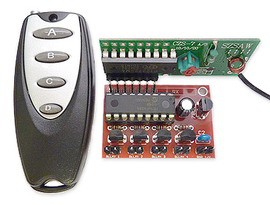
200m 4-Channel 433MHz Wireless RF Remote Control
Having the ability to control various appliances inside or outside of your house wirelessly is a huge convenience, and can make your life much easier and fun. RF remote control provides long range of up to 200m / 650ft and can find many uses for controlling different devices, and it works even through the walls. You can control lights, fans, AC system, computer, printer, amplifier, robots, garage door, security systems, motor-driven curtains, motorized window blinds, door locks, sprinklers, motorized projection screens and anything else you can think of. |
|
|
|