| |
The ESR meter is perfect for any electronics repair technicians, engineers or hobbyist. This handy meter measures electrolytic capacitor equivalent series resistance (ESR) in the circuit. ESR is a very important characteristic of capacitors greater than 1 microfarad. This meter makes measurements which are often impossible to check with standard digital capacitance meters.
Working:
The capacitance of the Device Under Test (DUT) is measured by finding the time taken to charge it to a particular voltage.
The Equivalent Series Resistance (ESR) of the DUT is measured by subjecting it to a pulse of known current, and finding the voltage developed across it.
Capacitance Measurement:
There are two ranges: A resistance of 4.7 Megohms is directly connected from the "hot" terminal of the DUT to the positive supply voltage. A resistance of 4.7 Kilohms can be connected to the positive rail by switching a transistor on.
Initially, the measurement is attempted with the 4.7K resistor. The time taken for the DUT to charge to a particular voltage is measured. If the result is too small, the resistor is switched off and the measurement is attempted again with the 4.7M resistor. Thus the two ranges differ by a factor of 1000.
ESR Measurement:
There are two ranges: First, a constant current source of about 5 mA is switched on and the voltage across the DUT is measured. If the reading is too low, the voltage reading is repeated with a current of 50 mA. Thus the two ranges differ by a factor of 10.
The DUT is discharged using one comparator in the LM339 as a switch. Adequate time has to be allowed in between readings in order to discharge the DUT fully.
The measurement of ESR is only valid for capacitors larger than about 10 microfarads or so. This is because smaller capacitors charge up from the pulse of current used to test them.
Principle of Measurement: Capacitance
The DUT is discharged to get rid of any charge it might have accumulated during the previous measurement cycle.
It is then connected to the positive rail through a 4.7 Kilohm resistor. Two comparators in the LM339 monitor the voltage on the DUT as it charges up.
The two comparators are connected as a window discriminator. The commoned output of these two comparators will be high when the input is above the lower threshold of around 10% supply voltage and go low when it crosses the higher threshold of around 50% supply voltage. The lower threshold has been used in order to obviate any errors due to the DUT not being discharged completely.
The width of the pulse of the window discriminator is proportional to the capacitance of the DUT. This is measured in a loop. Calibration is by adjusting the delays inside this loop, by padding it with goto's and nop's.
If the result points to a small value of capacitance, the measurement is attempted again with just the 4.7 Megohm resistor. This time, the pulse width is measured by a separate loop so that the range can be separately calibrated. This loop has the provision of compensating for the fixed capacitance of the circuit in parallel with the DUT (zeroing).
Principle of Measurement: Equivalent Series Resistance
Again, the DUT is discharged to get rid of any charge it might have accumulated during the previous measurement cycle.
It is then subjected to a short pulse of current - just long enough for the ADC inside the PIC to aquire a reading. Since the pulse is short, the capacitive part of the DUT is assumed to be uncharged. The voltage drop across the DUT is then contributed by its ESR alone. Thus the voltage read from the ADC is proportional to the ESR, and may be displayed as such.
This measurement is calibrated by adjusting the reference voltage applied to the internal ADC of the PIC.
Calibration
Take a good capacitor, around 100 or 1000 microfarads, and connect a small resistor, 10 or 5 ohms, in series with it. Connect to the meter and adjust that pot until the meter reads the resistance of that resistor. Repeat with other capacitors and resistors as a check on your calibration.
Limitations
Capacitors smaller than about 10 microfarads cannot be measured for ESR. Capacitance down to 10 picofarads may be measured, however. Devices with appreciable leakage cannot be measured at all for capacitance.
Notes
The instrument hangs for a long time if a large capacitor is connected while it is measuring in the low capacitance range.
Enhancements
A fast Sample-and-Hold Amplifier could be used ahead of the PIC analogue input in order to extend the measurement range of ESR to devices of lower capacitance.
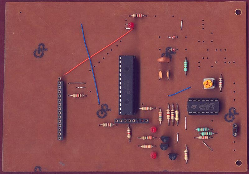
The device is a PIC16F876A. The circuit diagram shows it incorrectly as a plain 16F876.
In the overlay, there are a series of red lines which go nowhere(from a diagonal row of holes). These were originally there to connect a keypad or something, but I never could find sufficient functions or ranges that needed that extensive keypad. Just ignore them for the moment.
That row of dots near the head of the ic is for a programming header.
|
|
|
| |
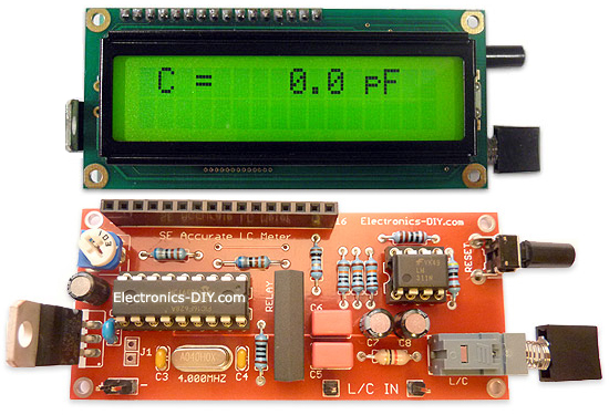
Accurate LC Meter
Build your own Accurate LC Meter (Capacitance Inductance Meter) and start making your own coils and inductors. This LC Meter allows to measure incredibly small inductances making it perfect tool for making all types of RF coils and inductors. LC Meter can measure inductances starting from 10nH - 1000nH, 1uH - 1000uH, 1mH - 100mH and capacitances from 0.1pF up to 900nF. The circuit includes an auto ranging as well as reset switch and produces very accurate and stable readings. |
|
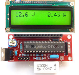
PIC Volt Ampere Meter
Volt Ampere Meter measures voltage of 0-70V or 0-500V with 100mV resolution and current consumption 0-10A or more with 10mA resolution. The meter is a perfect addition to any power supply, battery chargers and other electronic projects where voltage and current must be monitored. The meter uses PIC16F876A microcontroller with 16x2 backlighted LCD. |
|
|
|
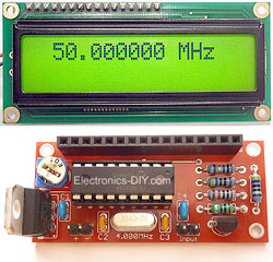
60MHz Frequency Meter / Counter
Frequency Meter / Counter measures frequency from 10Hz to 60MHz with 10Hz resolution. It is a very useful bench test equipment for testing and finding out the frequency of various devices with unknown frequency such as oscillators, radio receivers, transmitters, function generators, crystals, etc. |
|
1Hz - 2MHz XR2206 Function Generator
1Hz - 2MHz XR2206 Function Generator produces high quality sine, square and triangle waveforms of high-stability and accuracy. The output waveforms can be both amplitude and frequency modulated. Output of 1Hz - 2MHz XR2206 Function Generator can be connected directly to 60MHz Counter for setting precise frequency output. |
|
|
|
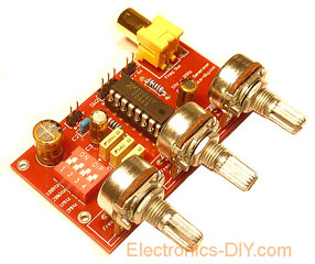
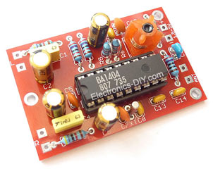
BA1404 HI-FI Stereo FM Transmitter
Be "On Air" with your own radio station! BA1404 HI-FI Stereo FM Transmitter broadcasts high quality stereo signal in 88MHz - 108MHz FM band. It can be connected to any type of stereo audio source such as iPod, Computer, Laptop, CD Player, Walkman, Television, Satellite Receiver, Tape Deck or other stereo system to transmit stereo sound with excellent clarity throughout your home, office, yard or camp ground. |
|
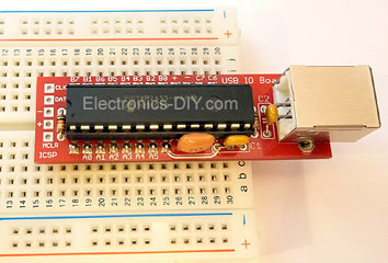
USB IO Board
USB IO Board is a tiny spectacular little development board / parallel port replacement featuring PIC18F2455/PIC18F2550 microcontroller. USB IO Board is compatible with Windows / Mac OSX / Linux computers. When attached to Windows IO board will show up as RS232 COM port. You can control 16 individual microcontroller I/O pins by sending simple serial commands. USB IO Board is self-powered by USB port and can provide up to 500mA for electronic projects. USB IO Board is breadboard compatible. |
|
|
|
|
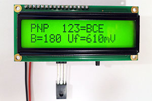
ESR Meter / Capacitance / Inductance / Transistor Tester Kit
ESR Meter kit is an amazing multimeter that measures ESR values, capacitance (100pF - 20,000uF), inductance, resistance (0.1 Ohm - 20 MOhm), tests many different types of transistors such as NPN, PNP, FETs, MOSFETs, Thyristors, SCRs, Triacs and many types of diodes. It also analyzes transistor's characteristics such as voltage and gain. It is an irreplaceable tool for troubleshooting and repairing electronic equipment by determining performance and health of electrolytic capacitors. Unlike other ESR Meters that only measure ESR value this one measures capacitor's ESR value as well as its capacitance all at the same time. |
|
Audiophile Headphone Amplifier Kit
Audiophile headphone amplifier kit includes high quality audio grade components such as Burr Brown OPA2134 opamp, ALPS volume control potentiometer, Ti TLE2426 rail splitter, Ultra-Low ESR 220uF/25V Panasonic FM filtering capacitors, High quality WIMA input and decoupling capacitors and Vishay Dale resistors. 8-DIP machined IC socket allows to swap OPA2134 with many other dual opamp chips such as OPA2132, OPA2227, OPA2228, dual OPA132, OPA627, etc. Headphone amplifier is small enough to fit in Altoids tin box, and thanks to low power consumption may be supplied from a single 9V battery. |
|
|
|
|
|
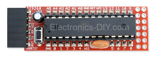
Arduino Prototype Kit
Arduino Prototype is a spectacular development board fully compatible with Arduino Pro. It's breadboard compatible so it can be plugged into a breadboard for quick prototyping, and it has VCC & GND power pins available on both sides of PCB. It's small, power efficient, yet customizable through onboard 2 x 7 perfboard that can be used for connecting various sensors and connectors. Arduino Prototype uses all standard through-hole components for easy construction, two of which are hidden underneath IC socket. Board features 28-PIN DIP IC socket, user replaceable ATmega328 microcontroller flashed with Arduino bootloader, 16MHz crystal resonator and a reset switch. It has 14 digital input/output pins (0-13) of which 6 can be used as PWM outputs and 6 analog inputs (A0-A5). Arduino sketches are uploaded through any USB-Serial adapter connected to 6-PIN ICSP female header. Board is supplied by 2-5V voltage and may be powered by a battery such as Lithium Ion cell, two AA cells, external power supply or USB power adapter. |
|
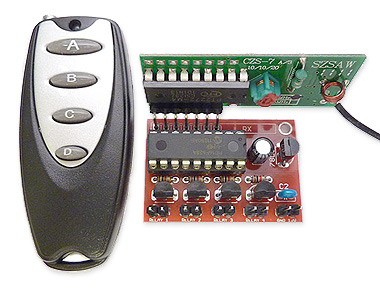
200m 4-Channel 433MHz Wireless RF Remote Control
Having the ability to control various appliances inside or outside of your house wirelessly is a huge convenience, and can make your life much easier and fun. RF remote control provides long range of up to 200m / 650ft and can find many uses for controlling different devices, and it works even through the walls. You can control lights, fans, AC system, computer, printer, amplifier, robots, garage door, security systems, motor-driven curtains, motorized window blinds, door locks, sprinklers, motorized projection screens and anything else you can think of. |
|
|
|