| |
One of the most useful gadgets a video enthusiast can have is a low-power TV Transmitter. Such a device can transmit a signal from a VCR to any TV in a home or backyard. Imagine the convenience of being able to sit by the pool watching your favorite movie on a portable with a tape or laser disc playing indoors. You could even retransmit cable TV for your own private viewing.
Videotapes can be dubbed from one VCR to another without a cable connecting the two machines together. When connected to a video camera, a TV transmitter can be used in surveillance for monitoring a particular location. The main problem a video enthusiast has in obtaining a TV transmitter is that a commercial units are expensive. However, we have some good news! You can build the TV Transmitter described here for less than $30 in one evening! The easiest way to do that is to order the kit that‚s available from the source given in the Parts List (a custom case for the kit is also available). Nevertheless, we present enough information here to build the TV Transmitter from scratch. The TV Transmitter combines linelevel audio and video signals, and transmits the resulting signal up to 300 feet. The circuit can be powered from a 9- volt battery. It is suggested that a 12-volt DC supply during be used during the alignment procedure. This would insure maximum transmission range and best possible picture. Aligning the TV Transmitter requires no special equipment whatsoever, and it is a very simple
procedure. The Transmitter's output can be tuned to be received on any TV channel from 2 to 6. The range of channels is wide enough so that the unit will not interfere with other TV viewers who are nearby. To comply with FCC rules, it is mandatory the nearby TV viewers are not disturbed by the transmission. If your activities interfere with the reception from a licensed station, regardless of the reason, you must shut down your unit.
Circuit Description
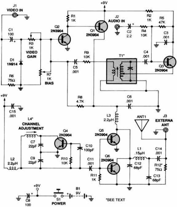
Above is the schematic diagram of the TV Transmitter circuit. Video signals input at jack J1 are first terminated by resistor R6 and coupled through capacitor C1 to clamping-diode D1. The clamping forces the sync pulses to a fixed DC level to reduce blooming effects. Potentiometer R3 is used to set the gain of the video signal; its effect is similar to that of the contrast control on a TV set. Bias-control R7 can be used to adjust the black level of the picture so that some level of signal is transmitted, even for a totally dark picture. That way, a TV receiver can maintain proper sync. As we'll get to later, potentiometers R3 and R7 are cross adjusted for the best all-around performance. RF-transformer T1 and its internal capacitor form the tank circuit of a Hartley oscillator that's tuned to 4.5 megahertz. Audio signals input at J2 are coupled to the base of Q3 via C2 and R4: the audio signal modulates the base signal of Q3 to form an audio subcarrier that‚s 4.5-megahertz higher than the video-carrier frequency. The FM modulated subcarrier is applied to the modulator section through C5 and R9. Resistor R9 adjusts the level of the subcarrier with respect to the video signal. Transistors Q1 and Q2 amplitude modulate the video and audio signals onto an RF-carrier signal. The operating frequency is set by coil L4, which is 3.5 turns of 24- gauge enameled wire on a form containing a standard ferrite slug.That coil is part of a Colpitts tank circuit also containing C7 and C9. The tank circuit forms Q4's feedback network, so Q4 oscillates at the set frequency The RF output from the oscillator section is amplified by Q5 and Q6, whose supply voltage comes from the modulator section. Antenna matching and low-pass filtering is performed by C12, C13, and L1. Resistor R12 is optional; it is added to help match the output signal to any kind of antenna. (More on that in a moment.)
Construction
Before we go on, while it is certainly possible to build the unit from scratch. However, unless you are an experienced builder and an accomplished parts scrounger, it is strongly recommended that you purchase the complete kit, or, at the very least, the component kit from the source mentioned in the Parts List. While most of the parts are readily available, some can be a real headache to obtain.
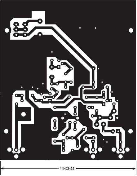
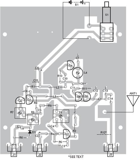
The 4.5-MHz RF transformer (T1) used in the kit is an OEM Toko part that is not available via traditional sources. While just about any 4.5-MHz RF transformer that is similar to the one described in the article (internal capacitor, tapped secondary) can be used, such units are hard to obtain from hobbyist-friendly sources. If you are determined to go that route, your best bet is to contact Toko directly (1250 Feehanville Dr.. Mt, Prospect, IL 60056; Tel. 708-297-0070) to obtain the location of your nearest full-line distributor. Also, coil L4 is a custom unit. It can, however, be home made using the parameters given earlier. The Transmitter should be built on a PC board for best performance. You can make a board from the foil pattern provided in Fig. 2, or use the one that’s included with the kit. Parts are installed on the board as shown in the parts-placement diagram [see Fig. 3). Pay careful attention to the orientation of the transistors, electrolytic capacitors. and the diode. If resistor R12 (not included in the kit) is used, it must be tack- soldered on the solder side of the board between the antenna output and ground. That resistor should be installed if you intend to use anything other than the built- in whip to provide proper matching between the antenna and the circuit.
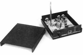
The outline of the switch (S1) that is shown in Fig. 3 is the same as the one that comes with the kit, an SPST push-button switch that is normally open. You can use any kind of toggle switch as a replacement. A simple whip antenna mounts to the board with a single machine screw: The whip antenna is suitable for most applications. The battery holder can be soldered to the board with scraps of jumper wire or mounted with doublesided tape or screws.When the board is finished, it must be mounted in a case. The case available from Ramsey Electronics allows the board to be mounted in the bottom half, and by lifting the top off, still be aligned. That also protects the underside of the board against shorts during alignment. You should inspect the solder side of the board carefully before mounting it in the case.
Alignment
To align the TV Transmitter, you'll need a TV receiver and a source of video such as a VCR or camcorder. You'll also need a non-metallic tool to adjust coil L4 and transformer T1. A fresh 9-volt battery can be used for alignment, but if you find it is difficult to align, try doing it with a 12-volt supply. Note that during alignment and testing, we found that the unit operated much better from 12 volts. If you find the same to be true, it is a simple matter to add an external power jack to the unit and wire it to the appropriate points on the PC board.
Tune a TV receiver to an unused channel between 2 and 6. The TV must have an indoor antenna
connected directly to it; an outdoor antenna or cable won't work. Make sure both potentiometers are in midposition and apply power to the Transmitter. Adjust L4 with a nonmetallic tool until the TV screen goes blank. Then fine-adjust L4 for the "most-blank" picture. Connect the video and audio outputs from a VCR to jacks J1 and J2 (respectively) of the Transmitter, Then set a video tape to play. You should see a picture on the TV screen:
if you do, readjust L4 for the best picture; if you don't, check the board for any bad connections. Next, adjust R3 for the best picture brightness and R7 for the best overall picture. You might have to make another minor adjustment to L4 after R3 and R7 are set. Finally, adjust T1 with a nonmetallic tool for the best sounding audio. That‚s all there is to it. The whip antenna should be fine for most in-home use. If you need more range, an external antenna can be connected to J3 (remember to install R12). But always keep in mind that it is your responsibility to make sure that your operation does not interfere with your neighbor's TV viewing.
PARTS LIST FOR THE TV TRANSMITTER
SEMICONDUCTORS
D1—1N914 silicon diode
Q1-Q—2N3904 NPN transistor
RESISTORS
(All fixed resistors are 1/4-watt, 5% units .)
R1, R2, R11—1000-ohm
R3, R7—1000-ohm trimmer potentiometer, PCmount
R4, R9, R10—10,000-ohm
R5—47,000-ohm
R6—75-ohm
R8—4700-ohm
R12—75-ohm (optional, see text)
CAPACITORS
C1, C8—100-mF, 16-WVDC, electrolytic
C2—2.2--mF, 50-WVDC, electrolytic
C3-C6, C11, C14, C15—001-mF, ceramic-disc
C7, C9—2.2-pF, ceramic-disc
C10—100-pF, ceramic-disc
C12, C13—68-pF, ceramic-disc
ADDITIONAL PARTS AND MATERIALS
ANT1—Antenna, telescopic-whip
B1—9-volt battery
J1-J3—RCA jack, PC-mount
L1—0.15-mH miniature inductor
L2, L3—2.2-mH miniature inductor
L4—0.14- to 0.24-mH adjustable, slug-tuned coil
(see text)
S1—SPST, push-button switch, normally open
T1—4.5-MHz 1F-can-style RF transformer (see
text)
Printed-circuit materials or pre-fab PC board, battery holder and connector, pair of RCA patch cords, solder, hardware, etc.
Related Links
Downloads
TV Transmitter - Link
|
|
|
| |
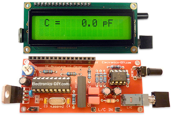
Accurate LC Meter
Build your own Accurate LC Meter (Capacitance Inductance Meter) and start making your own coils and inductors. This LC Meter allows to measure incredibly small inductances making it perfect tool for making all types of RF coils and inductors. LC Meter can measure inductances starting from 10nH - 1000nH, 1uH - 1000uH, 1mH - 100mH and capacitances from 0.1pF up to 900nF. The circuit includes an auto ranging as well as reset switch and produces very accurate and stable readings. |
|
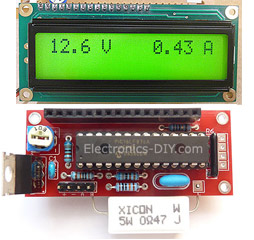
PIC Volt Ampere Meter
Volt Ampere Meter measures voltage of 0-70V or 0-500V with 100mV resolution and current consumption 0-10A or more with 10mA resolution. The meter is a perfect addition to any power supply, battery chargers and other electronic projects where voltage and current must be monitored. The meter uses PIC16F876A microcontroller with 16x2 backlighted LCD. |
|
|
|
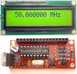
60MHz Frequency Meter / Counter
Frequency Meter / Counter measures frequency from 10Hz to 60MHz with 10Hz resolution. It is a very useful bench test equipment for testing and finding out the frequency of various devices with unknown frequency such as oscillators, radio receivers, transmitters, function generators, crystals, etc. |
|
1Hz - 2MHz XR2206 Function Generator
1Hz - 2MHz XR2206 Function Generator produces high quality sine, square and triangle waveforms of high-stability and accuracy. The output waveforms can be both amplitude and frequency modulated. Output of 1Hz - 2MHz XR2206 Function Generator can be connected directly to 60MHz Counter for setting precise frequency output. |
|
|
|
BA1404 HI-FI Stereo FM Transmitter
Be "On Air" with your own radio station! BA1404 HI-FI Stereo FM Transmitter broadcasts high quality stereo signal in 88MHz - 108MHz FM band. It can be connected to any type of stereo audio source such as iPod, Computer, Laptop, CD Player, Walkman, Television, Satellite Receiver, Tape Deck or other stereo system to transmit stereo sound with excellent clarity throughout your home, office, yard or camp ground. |
|
USB IO Board
USB IO Board is a tiny spectacular little development board / parallel port replacement featuring PIC18F2455/PIC18F2550 microcontroller. USB IO Board is compatible with Windows / Mac OSX / Linux computers. When attached to Windows IO board will show up as RS232 COM port. You can control 16 individual microcontroller I/O pins by sending simple serial commands. USB IO Board is self-powered by USB port and can provide up to 500mA for electronic projects. USB IO Board is breadboard compatible. |
|
|
|
|
ESR Meter / Capacitance / Inductance / Transistor Tester Kit
ESR Meter kit is an amazing multimeter that measures ESR values, capacitance (100pF - 20,000uF), inductance, resistance (0.1 Ohm - 20 MOhm), tests many different types of transistors such as NPN, PNP, FETs, MOSFETs, Thyristors, SCRs, Triacs and many types of diodes. It also analyzes transistor's characteristics such as voltage and gain. It is an irreplaceable tool for troubleshooting and repairing electronic equipment by determining performance and health of electrolytic capacitors. Unlike other ESR Meters that only measure ESR value this one measures capacitor's ESR value as well as its capacitance all at the same time. |
|
Audiophile Headphone Amplifier Kit
Audiophile headphone amplifier kit includes high quality audio grade components such as Burr Brown OPA2134 opamp, ALPS volume control potentiometer, Ti TLE2426 rail splitter, Ultra-Low ESR 220uF/25V Panasonic FM filtering capacitors, High quality WIMA input and decoupling capacitors and Vishay Dale resistors. 8-DIP machined IC socket allows to swap OPA2134 with many other dual opamp chips such as OPA2132, OPA2227, OPA2228, dual OPA132, OPA627, etc. Headphone amplifier is small enough to fit in Altoids tin box, and thanks to low power consumption may be supplied from a single 9V battery. |
|
|
|
|
|
Arduino Prototype Kit
Arduino Prototype is a spectacular development board fully compatible with Arduino Pro. It's breadboard compatible so it can be plugged into a breadboard for quick prototyping, and it has VCC & GND power pins available on both sides of PCB. It's small, power efficient, yet customizable through onboard 2 x 7 perfboard that can be used for connecting various sensors and connectors. Arduino Prototype uses all standard through-hole components for easy construction, two of which are hidden underneath IC socket. Board features 28-PIN DIP IC socket, user replaceable ATmega328 microcontroller flashed with Arduino bootloader, 16MHz crystal resonator and a reset switch. It has 14 digital input/output pins (0-13) of which 6 can be used as PWM outputs and 6 analog inputs (A0-A5). Arduino sketches are uploaded through any USB-Serial adapter connected to 6-PIN ICSP female header. Board is supplied by 2-5V voltage and may be powered by a battery such as Lithium Ion cell, two AA cells, external power supply or USB power adapter. |
|
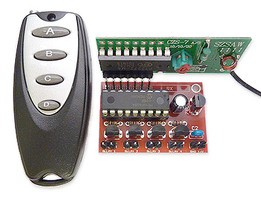
200m 4-Channel 433MHz Wireless RF Remote Control
Having the ability to control various appliances inside or outside of your house wirelessly is a huge convenience, and can make your life much easier and fun. RF remote control provides long range of up to 200m / 650ft and can find many uses for controlling different devices, and it works even through the walls. You can control lights, fans, AC system, computer, printer, amplifier, robots, garage door, security systems, motor-driven curtains, motorized window blinds, door locks, sprinklers, motorized projection screens and anything else you can think of. |
|
|
|