| |
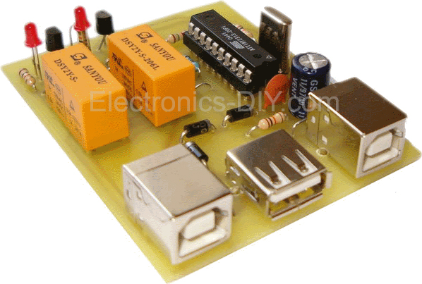
USB switch is used to share USB devices such as printers, scanners, hard drivers, etc. between two computers. Just connect the two computers on a network device and say the printer as shared. This method however requires the continued operation of the computer we plugged the printer. Solution to above problem is to give the circuit that we present, and has the potential to be transferred to the printer on whichever computer we want, because the printer is connected to one of two computers, but in construction.

With lower prices on laptop computers became affordable sailer acquisition and the average Greek. Getting two computers, however, automatically generated and the need to link them with the most common peripherals already available, such as a printer, a scanner , the WEB Camera , the ISDN netMod and more. To select the type of interface with computer peripheral into account that we have the most modern peripherals are interconnected USB , leading us to this choice. As regional USB to mention the USB printer. The position may well be a scanner , a camera or other device is USB , preferably low-speed USB 1.1 (01/05 Mbps ), this does not mean it can not work with devices and USB 2.0. Since we manufacture include mechanical parts, you may create problems in some regional communication through the floor construction, because of both high speed as this USB 2.0 (480 Mbps ) and "noise" generated in the contacts of the relay. According to the block diagram of Figure 1 , the printer is connected to computer # 1 and the No. 2 microprocessor computer. When given the mandate by the software to manufacturing ( USBswitch . exe ), is the cross-switching devices and the printer is now No. 2 on the computer and the microcontroller to the computer # 1.
The theoretical circuit The circuit consists of a few parts of the microcontroller IC 1 to take control of where it is attached printer, and is responsible for communicating with software on the computer through the port USB . The supply of construction made from doors USB and two computers, as well as provide voltage 5 V with a maximum current of 500 mA each, capable of not only the power of our workmanship but also the peripheral to be connected. Moreover, this ensures the smooth operation of our manufacturing where we have a single computer. The data signals D + and D - channel USB are level 0 and +3.3 V . The IC 1 levels but works with TTL 0 and five V . So there are two ways to adapt: either to build a converter station from the five V to 3.3 V and back to the data bus D + and D - or down the voltage supplied to the IC in the 1st 03/03 V when the signal level is between 0 and 03/03 V . The Atmel We guarantee that the operating voltage of a ATtiny 07/02 is between 2 313 V and 5.5 V , so we chose the second way, namely the operation of the IC on the 1st at 3.3 V . Instead of a stabilizer in 3/3 V chose three routes the 1st N 4 001 ( D five - D 7) are in the right time creates a voltage drop .7 V so VCC = five - (0.7 * 3) = 2.9 V . This in theory because in practice the tendency is almost on the 3rd V . The specification of the channel USB devices for low-speed 07/02 - 03.06 V so that the three V is enough. The R is the 6th load resistance to ensure the circuit always 3 V . The relay RE 1 and RE on the 2nd take the link IC to the first one, and the printer to the second computer. The RE 1 working backwards from RE 2. That is reinforced when the RE a, the RE is disarmed two, and vice versa. When the base of the T on the 1st we have 0 V , the transistor will not conduct a collector and thus will have 5 V winding through the RE an. This trend is on the 5th of V led to the base of T2 putting a state conductivity. By the same logic when the base of T1 will have the 3rd V , will pass a state conductivity dropping the voltage of the collector to 0 V and thus drive the RE two disarm. The diodes D 1, D 3 are used to protect the T1 and T2 of the reverse currents generated in the windings of RE 1 and RE on the 2nd. The LEDs D the 2nd, D the 4th is indicative of the status of each relay ( ON - OFF ). The relays have a rated voltage of 6 V DC and consumption is a ~ 20 mA . For this reason we chose to arm only one at a time and not to arm or disarm both simultaneously, thus reducing the overall power consumption of the circuit. The R 7, R 8 is terminating resistors channel USB . In R the 9th Poles D - port of USB in the three V thereby indicating the existence of device USB low speed (5/1 Mbps ). Construction of the circuit The construction of the circuit will not be a problem because of its simplicity. Little attention should be paid to the polarity of the materials (diodes, capacitors, integrated). Glue the first shorter and smaller components and then the bigger and taller. The black lines connecting the holes in the plan of placing materials are wire bridges on top of the board. The LEDs D 3, D the 4th and resistors R an, R two can not be placed on reducing the power consumption at 6 mA . If you can not find ATtiny 2,313 on the market, you in position to schedule the same files . hex and . EEP an AT ninety S two thousand three hundred thirteen and put on the same basis as they have the same layout on the pins. If, after connecting the peripheral to the computer, show you the message that found an unknown device and you've already installed drivers will need to remove one of the diodes D 5 and D the 6th or D and the 7th position of sticking a wire bridge. With this conversion will increase the voltage VCC of the three V to 3.7 V , sufficient for the proper functioning of AT ninety S two thousand three hundred thirteen. The AT ninety S two thousand three hundred thirteen can operate from 2.7 V - 6 V . Then what is the reason to move up the voltage to 3.7 V and can operate with 02.07 V ? The reason is simple. The operating voltage of 2.7 V applied as the maximum operating frequency, which is the 10th MHz . In our case, however, the operating frequency has increased on the 12th in MHz or 20% more ( overclocking ). For this reason we can not work at lower voltage. On the other hand, ATtiny two thousand three hundred and thirteen is the maximum frequency of operation on the 20th MHz so we can comfortably operate at 2.7 V . Programming IC1 The microcontroller IC 1 should be programmed with two files. The memory flash you should plan to file USBswitch . hex and internal memory eeprom to file USBswitch . EEP . If you do choose ATtiny two thousand three hundred and thirteen against AT ninety S will have two thousand three hundred thirteen of the area < Fuses > programmer you can be sure that option is checked < Ext . Crystal OSC.? eight Frequency - MHz? Start-up Time fourteen CK + sixty-five MS? (CKSEL = 1,111 = the 11th SUT) >. This will have to check because this microcontroller has the ability to activate the internal oscillator 0.128 - 8 MHz , and should make sure that is selected using the external crystal frequencies on the 8th of MHz and above. Operation When connected to our building a free port USB computer through the door K1, the computer will recognize a new device and will ask drivers ( Drivers ). The driver for device ' USB Switch 'is in the folder' Driver 'and consists of three files: AVR three hundred and nine. DLL , AVR 309. INF and AVR 309. sys . After installing the drivers, the device will be ready for use. And both computers must have installed the drivers and the program ' USBswitch . exe '. When you connect both computers to our device, install drivers and run the program USBswitch . exe , we see that in a computer would see the message of Figure 3 and in another the message of Figure 4 . One that will display the message in Figure 3 will be connected to the printer. In this case, as you can see the button "Connect to a common regional" is disabled because we have already connected the printer to this computer. In the case of Figure 4, the program informs us that the device " USB Switch " that is essentially the IC one, has been found and you can press the button "Connect to a common regional USB 'to the IC on the 1st to change the status of relay switched to the printer on this computer. If you do not install the driver, can not run the program.
MATERIALS
C1: 100nF
C2: 470mF/16V
C3: the 22nd pF
C4: the 22nd pF
D1, D3: an N 4148
D2, D4: LED
D5, D6, D7: 1N4001
IC1: ATTINY2313 ( see text )
K1: plug board USB-B
K2: Connector board USB-A
K3: plug board USB-B
R1, R2: 1k
R3, R4, R5, R6: 10K
R7, R8: 56R
R9: 1k5
RE the 1st, RE 2: Relay on the 6th V , duplicate contacts.
T1, T2: BC547
X1 : the 12th MHz
Cost of materials: 20 €
Difficulty of manufacture: *Inaccessible materials: *
Download code of the program management and driver (driver) of the USB Switch below.
|
|
|
| |
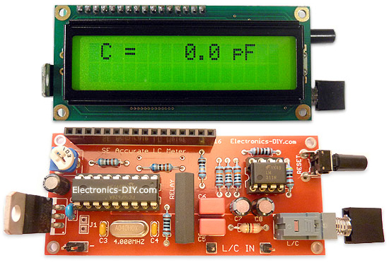
Accurate LC Meter
Build your own Accurate LC Meter (Capacitance Inductance Meter) and start making your own coils and inductors. This LC Meter allows to measure incredibly small inductances making it perfect tool for making all types of RF coils and inductors. LC Meter can measure inductances starting from 10nH - 1000nH, 1uH - 1000uH, 1mH - 100mH and capacitances from 0.1pF up to 900nF. The circuit includes an auto ranging as well as reset switch and produces very accurate and stable readings. |
|
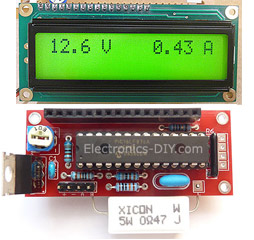
PIC Volt Ampere Meter
Volt Ampere Meter measures voltage of 0-70V or 0-500V with 100mV resolution and current consumption 0-10A or more with 10mA resolution. The meter is a perfect addition to any power supply, battery chargers and other electronic projects where voltage and current must be monitored. The meter uses PIC16F876A microcontroller with 16x2 backlighted LCD. |
|
|
|
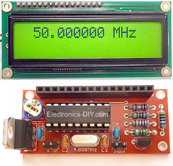
60MHz Frequency Meter / Counter
Frequency Meter / Counter measures frequency from 10Hz to 60MHz with 10Hz resolution. It is a very useful bench test equipment for testing and finding out the frequency of various devices with unknown frequency such as oscillators, radio receivers, transmitters, function generators, crystals, etc. |
|
1Hz - 2MHz XR2206 Function Generator
1Hz - 2MHz XR2206 Function Generator produces high quality sine, square and triangle waveforms of high-stability and accuracy. The output waveforms can be both amplitude and frequency modulated. Output of 1Hz - 2MHz XR2206 Function Generator can be connected directly to 60MHz Counter for setting precise frequency output. |
|
|
|
BA1404 HI-FI Stereo FM Transmitter
Be "On Air" with your own radio station! BA1404 HI-FI Stereo FM Transmitter broadcasts high quality stereo signal in 88MHz - 108MHz FM band. It can be connected to any type of stereo audio source such as iPod, Computer, Laptop, CD Player, Walkman, Television, Satellite Receiver, Tape Deck or other stereo system to transmit stereo sound with excellent clarity throughout your home, office, yard or camp ground. |
|
USB IO Board
USB IO Board is a tiny spectacular little development board / parallel port replacement featuring PIC18F2455/PIC18F2550 microcontroller. USB IO Board is compatible with Windows / Mac OSX / Linux computers. When attached to Windows IO board will show up as RS232 COM port. You can control 16 individual microcontroller I/O pins by sending simple serial commands. USB IO Board is self-powered by USB port and can provide up to 500mA for electronic projects. USB IO Board is breadboard compatible. |
|
|
|
|
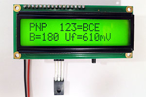
ESR Meter / Capacitance / Inductance / Transistor Tester Kit
ESR Meter kit is an amazing multimeter that measures ESR values, capacitance (100pF - 20,000uF), inductance, resistance (0.1 Ohm - 20 MOhm), tests many different types of transistors such as NPN, PNP, FETs, MOSFETs, Thyristors, SCRs, Triacs and many types of diodes. It also analyzes transistor's characteristics such as voltage and gain. It is an irreplaceable tool for troubleshooting and repairing electronic equipment by determining performance and health of electrolytic capacitors. Unlike other ESR Meters that only measure ESR value this one measures capacitor's ESR value as well as its capacitance all at the same time. |
|
Audiophile Headphone Amplifier Kit
Audiophile headphone amplifier kit includes high quality audio grade components such as Burr Brown OPA2134 opamp, ALPS volume control potentiometer, Ti TLE2426 rail splitter, Ultra-Low ESR 220uF/25V Panasonic FM filtering capacitors, High quality WIMA input and decoupling capacitors and Vishay Dale resistors. 8-DIP machined IC socket allows to swap OPA2134 with many other dual opamp chips such as OPA2132, OPA2227, OPA2228, dual OPA132, OPA627, etc. Headphone amplifier is small enough to fit in Altoids tin box, and thanks to low power consumption may be supplied from a single 9V battery. |
|
|
|
|
|
Arduino Prototype Kit
Arduino Prototype is a spectacular development board fully compatible with Arduino Pro. It's breadboard compatible so it can be plugged into a breadboard for quick prototyping, and it has VCC & GND power pins available on both sides of PCB. It's small, power efficient, yet customizable through onboard 2 x 7 perfboard that can be used for connecting various sensors and connectors. Arduino Prototype uses all standard through-hole components for easy construction, two of which are hidden underneath IC socket. Board features 28-PIN DIP IC socket, user replaceable ATmega328 microcontroller flashed with Arduino bootloader, 16MHz crystal resonator and a reset switch. It has 14 digital input/output pins (0-13) of which 6 can be used as PWM outputs and 6 analog inputs (A0-A5). Arduino sketches are uploaded through any USB-Serial adapter connected to 6-PIN ICSP female header. Board is supplied by 2-5V voltage and may be powered by a battery such as Lithium Ion cell, two AA cells, external power supply or USB power adapter. |
|
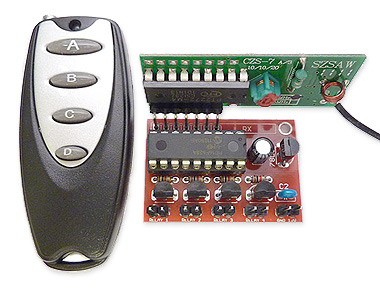
200m 4-Channel 433MHz Wireless RF Remote Control
Having the ability to control various appliances inside or outside of your house wirelessly is a huge convenience, and can make your life much easier and fun. RF remote control provides long range of up to 200m / 650ft and can find many uses for controlling different devices, and it works even through the walls. You can control lights, fans, AC system, computer, printer, amplifier, robots, garage door, security systems, motor-driven curtains, motorized window blinds, door locks, sprinklers, motorized projection screens and anything else you can think of. |
|
|
|