| |
MAX16834 High Power LED Driver |
|
There is a major advantage to using LEDs for lighting: various dimming techniques allow seamless control of the light output from the LED source. While LEDs are efficient light sources, the dimming feature also allows for considerable power savings. Control over the light output also helps to set the desired ambience.
PWM dimming is preferred to analog dimming for several reasons. For many applications PWM dimming maintains the color of the light output regardless of the dim level. For circuit design, PWM control is more immune to noise; the control signal need not be accurate in both voltage levels and dimming frequency; and the driver circuit design is less complex. PWM dimming usually requires a control line that carries the PWM dimming signal, in addition to the two power-supply lines. This standard configuration is, however, a drawback for applications that use common dimming for a large number of lights; the configuration also makes it difficult to replace the incandescent light installations with two-wire supply lines that depend on supply chopping for dimming control.
Traditional, crude LED driver circuits that work with power-supply dimming are problematic. Those drivers turn off power to the LEDs gradually as the input filter capacitors discharge to the minimum operating voltage of the driver. That process can cause the input and output filter capacitors to discharge to low levels. Then when the supply is turned back on, a huge surge of current flows to replenish the capacitor charge, thus causing EMI issues and premature dimmer damage. To prevent these various issues, those circuits use large inductor filters that increase cost.
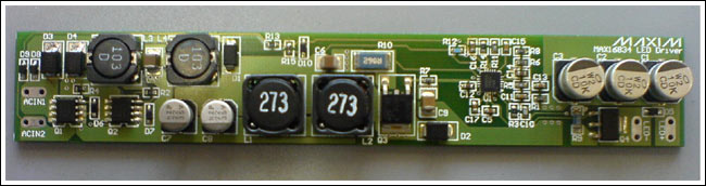
The LED driver reference design described here addresses this basic design challenge with PWM dimming. This LED driver implements PWM dimming based on supply chopping; it does not cause any supply current overshoot. The design provides up to 90% efficiency while operating from a 24V supply. It allows a unidirectional supply input with an efficient semi-MOSFET bridge rectifier at the input. Figure 1 shows the top view of the design board.
Important design features
±24VDC ±5% unidirectional power-supply input
Drives LED strings with forward voltages up to 60V
700mA LED current
Input supply-chopped dimming
UVLO at 21V
LED open protection at 65V
As low as 5% dimming at 330Hz dimming frequency
Greater than 90% efficiency
More detailed image (PDF, 2.61MB)
Figure 1. Reference design board (top view). The board size is 23mm x 138mm, in two layers, with components on the top side only.
Components list
Designator Part Package Quantity
C1, C2, C3 10µF, 80V, EEEFK1K100XP CAP_CD8X6.2 3
C4, C6 4.7µF, 50V 1210 2
C5, C13 0.22µF, 16V 0603 2
C7, C8 22µF, 35V, EEEFK1V220R CAP_WF6.3 2
C9 1µF, 100V, X7R ceramic 1210 1
C11 6.8nF, X7R ceramic 0603 1
C12, C14 1µF, 16V, X7R ceramic 0603 2
C15 2.2nF, X7R ceramic 0603 1
C16 0.22µF, 16V, X7R ceramic 0603 1
C17 0.1µF, X7R ceramic 0603 1
D1 B130 SMA 1
D2 B180 SMB 1
D3, D4 B330 SMA 2
D5, D8, D9 1N4148WS SOD323 3
D6, D7 UDZST179.1V SOD323 2
D10 UDZST174.3V SOD323 1
L1, L2 27µH, MSS1246 MSS1246 2
L3, L4 10µH, MSS1038 MSS1038 2
Q1, Q2 Si4446DY SO-8 2
Q3 STD15NF10 DPAK 1
Q4 FQT7N10LTF SOT223-4 1
R1 442kΩ 1% 0603 1
R2, R3, R4, R13, R14 10kΩ 1% 0603 5
R5 274Ω, 1% 0603 1
R6 26.7kΩ 1% 0603 1
R7 1Ω 0603 1
R8 10.5kΩ 1% 0603 1
R9 0.15Ω, 1% 1206 1
R10 0.062Ω, 1% 2512 1
R11 20kΩ 1% 0603 1
R12 137kΩ 1% 0603 1
R15 1kΩ 1% 0603 1
U1 MAX16834 4mm x 4mm, 20-pin TQFN-EP 1
More detailed image (PDF, 236kB)
Figure 2. Circuit schematic for the reference design features the MAX16834.
Detailed description
This LED driver reference design uses a boost converter topology to drive a constant current to the LED load. The boost topology is suitable for this design, as the LED forward voltage is always above the input voltage. The MAX16834 provides all the necessary features to implement this boost-type LED driver with very efficient PWM dimming. Other popular topologies like buck-boost, SEPIC, or high-side buck can be implemented using the MAX16834 with equal ease.
Figure 2 shows the circuit schematic for this LED driver application. To make the power-supply input unidirectional, a bridge rectifier is used at the input. The bridge rectifier uses a 2-diode, 2-MOSFET (n-channel) configuration to reduce voltage drop and power dissipation in the input bridge. Diodes D3 and D4 are not replaced with p-channel MOSFETS, as this configuration would cause the input supply capacitors to discharge during a PWM off (supply off) condition and thus produce large inrush currents. An input filter comprising L3, C4, L4, C6, C7, and C8 limits the switching frequency components in the input current to very low values. During PWM dimming, electrolytic capacitors are used for input and output filtering to avoid any audible noise—a problematic characteristic of high-value ceramic capacitors.
This boost-type LED driver operates at a switching frequency of 250kHz in continuous-conduction mode. A peak-to-peak ripple current of 30% is selected for the inductor. Reduced inductor current ripple increases efficiency, reduces noise, and stabilizes the current control loop. But these advantages do come with reduced system bandwidth because of the reduced right-half-plane zero frequency. With a conventional LED driver, reduced bandwidth affects PWM dimming. But the MAX16834 incorporates a specific feedback topology to address this issue, and consequently provides a best-in-class PWM dimming response without compromising stability.
The boost converter output (i.e., LED+ node), with respect to the driver ground, is connected to the anode of the LED string. The LED cathode is connected to ground through the dimming MOSFET, Q4, and the LED current-sense resistor, R9. Q4 is turned on and off during PWM dimming. R9 provides the LED current information to the MAX16834; it thus regulates the LED current by controlling the boost converter.
Undervoltage lockout (UVLO)
The LED driver is turned on when the supply voltage (VIN node) is above 21V. This ensures that the converter, which is optimized for this minimum supply input, does not start before the input voltage settles. The filter capacitor, C16, filters any noise spikes that can cause the UVLO to activate by mistake.
Slope compensation
As the boost converter used in this driver operates in CCM with more than 50% duty cycle, the internal inductor current-control loop can become unstable and cause subharmonic oscillations unless slope compensation is implemented. A single capacitor, C15, from the SC pin to ground adds the necessary slope to the current-sense waveforms for slope compensation. Refer to the MAX16834 data sheet for more details on the design of slope compensation capacitor.
Feedback compensation
The boost-converter, power-circuit transfer function has a right-half-plane zero due to the boost topology; the CCM operation; and an output pole caused by the output filter capacitors, LED dynamic impedance, and the LED current-sense resistor. The feedback compensation network, consisting of R5, C13, and C7 from the COMP pin to ground, introduces a pole at the origin, a zero at the output pole frequency, and a high-frequency pole.
The compensation zero cancels the output pole and maintains the slope of the system’s gain-frequency response to -20dB/decade. The total loop gain of the system should cross 0dB gain at a -20dB/decade slope below one-fifth of the right-half-plane zero frequency to stabilize the system and to have sufficient phase margin. The compensation resistor sets the error-amplifier gain above the compensating zero frequency so that the above condition for stability is satisfied. Compensation capacitor C11 introduces a pole at half the switching frequency to provide attenuation to high-frequency components and noise. Refer to the MAX16834 data sheet for more details on the design of feedback compensation.
Supply-chopped PWM dimming
Supply-chopped PWM dimming is used in this design: to reduce another input line for a dim signal and to enable existing dimming solutions that use power-supply chopping. Popular DC dimmer circuits implement dimming by employing an n-channel MOSFET at the return path of the power-supply input to the LED driver that alternately turns on and off with the dimming control. This design breaks the current flow to the LED driver alternately, and makes the ground input float.
To obtain a negligible inrush current when the dimmer turns back on, the filter capacitors in the LED driver should maintain their charge throughout the PWM off period. Now with very little charge replenishing, the capacitor voltages should return to their normal level with out causing any inrush current. This LED driver quickly detects when a power supply turns off during PWM dimming, and then it turns off the LED current. With PWM off, resistors R13 and R15 discharge any capacitance at the input and the DIM pin is made low. This approach works the same regardless of the direction of the input power supply. A low at the DIM pin instantly turns off the LED current by turning off the dimming MOSFET Q4.
When the DIM input is disabled, the MAX16834 consumes very little power as the boost converter is also turned off; it need not wait for the feedback to respond. Meanwhile, a switch at the output of the error amplifier holds the last point of stable feedback as charge, stored in compensation capacitors C13 and C11. The next time that the power-supply input is turned on, the error-amplifier output immediately jumps to the previous stable state, thereby causing the LED current to reach the set value almost instantly.
Overvoltage protection (OVP)
In the event of an open-LED condition, the output voltage of the boost converter can reach unsafe levels unless it is protected. The MAX16834 incorporates OVP: the boost converter is turned off, if the voltage at the OVP pin increases beyond 1.435V. The boost converter is restarted once the voltage at the OVP pin falls below the lower threshold. This restart feature enables LED current as soon as the LED is reconnected. A filter capacitor, C10, ensures that the OVP is not triggered by noise.
Test results
Figures 3 through 8 show the test results for this reference design.
Figure 3. LED voltage at startup with respect to ground.
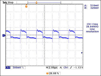
Figure 4. LED voltage ripple (voltage at LED+).
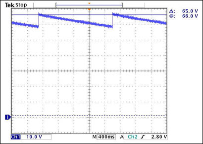
Figure 5. Open LED OVP (voltage at LED+).
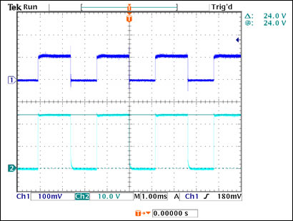
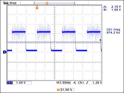
Figure 6. LED current measured across resistor R9 (150mΩ) and chopped input-supply voltage.
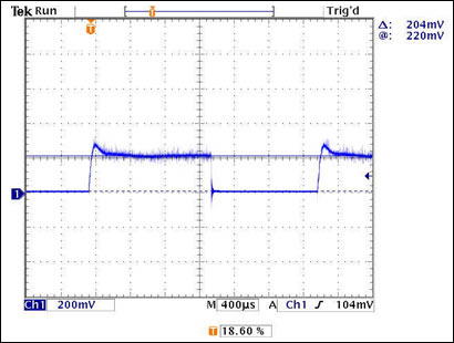
Figure 7. Input-supply current: measured across a 0.1#937; resistor.
Figure 8. Voltage at the PWMDIM pin.
Power-up procedure
Use the following steps to power-up the board for the reference design.
Connect an LED string, with a forward voltage between 50V and 60V and a current rating between 700mA and 1A, to the LED+ and LED- terminals on the board.
Connect a power supply with a rating of 0 to 30V and 3A minimum to ACIN1 and ACIN2 in any direction.
Increase the supply voltage gradually to 22V. At about 21V the converter will start and the LED string will be driven with a 700mA current.
To start PWM dimming, chop the supply at 100Hz to 1kHz frequency with the desired duty cycle.
|
|
|
| |
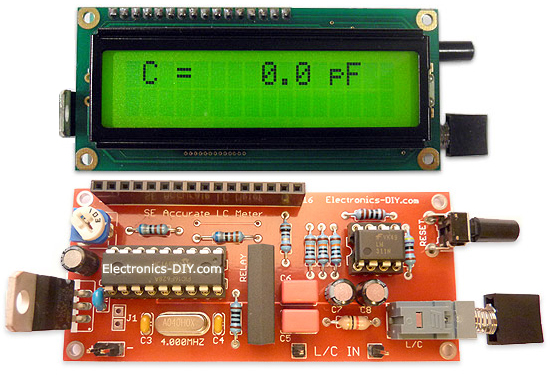
Accurate LC Meter
Build your own Accurate LC Meter (Capacitance Inductance Meter) and start making your own coils and inductors. This LC Meter allows to measure incredibly small inductances making it perfect tool for making all types of RF coils and inductors. LC Meter can measure inductances starting from 10nH - 1000nH, 1uH - 1000uH, 1mH - 100mH and capacitances from 0.1pF up to 900nF. The circuit includes an auto ranging as well as reset switch and produces very accurate and stable readings. |
|
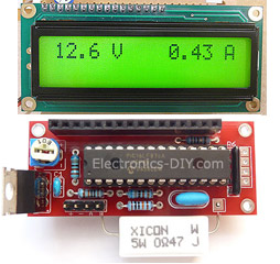
PIC Volt Ampere Meter
Volt Ampere Meter measures voltage of 0-70V or 0-500V with 100mV resolution and current consumption 0-10A or more with 10mA resolution. The meter is a perfect addition to any power supply, battery chargers and other electronic projects where voltage and current must be monitored. The meter uses PIC16F876A microcontroller with 16x2 backlighted LCD. |
|
|
|
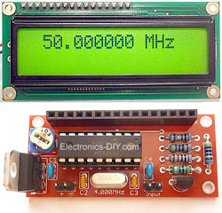
60MHz Frequency Meter / Counter
Frequency Meter / Counter measures frequency from 10Hz to 60MHz with 10Hz resolution. It is a very useful bench test equipment for testing and finding out the frequency of various devices with unknown frequency such as oscillators, radio receivers, transmitters, function generators, crystals, etc. |
|
1Hz - 2MHz XR2206 Function Generator
1Hz - 2MHz XR2206 Function Generator produces high quality sine, square and triangle waveforms of high-stability and accuracy. The output waveforms can be both amplitude and frequency modulated. Output of 1Hz - 2MHz XR2206 Function Generator can be connected directly to 60MHz Counter for setting precise frequency output. |
|
|
|
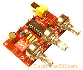
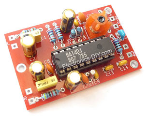
BA1404 HI-FI Stereo FM Transmitter
Be "On Air" with your own radio station! BA1404 HI-FI Stereo FM Transmitter broadcasts high quality stereo signal in 88MHz - 108MHz FM band. It can be connected to any type of stereo audio source such as iPod, Computer, Laptop, CD Player, Walkman, Television, Satellite Receiver, Tape Deck or other stereo system to transmit stereo sound with excellent clarity throughout your home, office, yard or camp ground. |
|
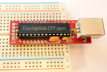
USB IO Board
USB IO Board is a tiny spectacular little development board / parallel port replacement featuring PIC18F2455/PIC18F2550 microcontroller. USB IO Board is compatible with Windows / Mac OSX / Linux computers. When attached to Windows IO board will show up as RS232 COM port. You can control 16 individual microcontroller I/O pins by sending simple serial commands. USB IO Board is self-powered by USB port and can provide up to 500mA for electronic projects. USB IO Board is breadboard compatible. |
|
|
|
|
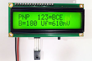
ESR Meter / Capacitance / Inductance / Transistor Tester Kit
ESR Meter kit is an amazing multimeter that measures ESR values, capacitance (100pF - 20,000uF), inductance, resistance (0.1 Ohm - 20 MOhm), tests many different types of transistors such as NPN, PNP, FETs, MOSFETs, Thyristors, SCRs, Triacs and many types of diodes. It also analyzes transistor's characteristics such as voltage and gain. It is an irreplaceable tool for troubleshooting and repairing electronic equipment by determining performance and health of electrolytic capacitors. Unlike other ESR Meters that only measure ESR value this one measures capacitor's ESR value as well as its capacitance all at the same time. |
|
Audiophile Headphone Amplifier Kit
Audiophile headphone amplifier kit includes high quality audio grade components such as Burr Brown OPA2134 opamp, ALPS volume control potentiometer, Ti TLE2426 rail splitter, Ultra-Low ESR 220uF/25V Panasonic FM filtering capacitors, High quality WIMA input and decoupling capacitors and Vishay Dale resistors. 8-DIP machined IC socket allows to swap OPA2134 with many other dual opamp chips such as OPA2132, OPA2227, OPA2228, dual OPA132, OPA627, etc. Headphone amplifier is small enough to fit in Altoids tin box, and thanks to low power consumption may be supplied from a single 9V battery. |
|
|
|
|
|
Arduino Prototype Kit
Arduino Prototype is a spectacular development board fully compatible with Arduino Pro. It's breadboard compatible so it can be plugged into a breadboard for quick prototyping, and it has VCC & GND power pins available on both sides of PCB. It's small, power efficient, yet customizable through onboard 2 x 7 perfboard that can be used for connecting various sensors and connectors. Arduino Prototype uses all standard through-hole components for easy construction, two of which are hidden underneath IC socket. Board features 28-PIN DIP IC socket, user replaceable ATmega328 microcontroller flashed with Arduino bootloader, 16MHz crystal resonator and a reset switch. It has 14 digital input/output pins (0-13) of which 6 can be used as PWM outputs and 6 analog inputs (A0-A5). Arduino sketches are uploaded through any USB-Serial adapter connected to 6-PIN ICSP female header. Board is supplied by 2-5V voltage and may be powered by a battery such as Lithium Ion cell, two AA cells, external power supply or USB power adapter. |
|
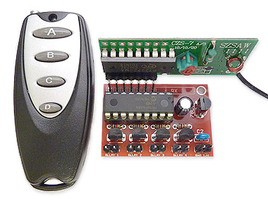
200m 4-Channel 433MHz Wireless RF Remote Control
Having the ability to control various appliances inside or outside of your house wirelessly is a huge convenience, and can make your life much easier and fun. RF remote control provides long range of up to 200m / 650ft and can find many uses for controlling different devices, and it works even through the walls. You can control lights, fans, AC system, computer, printer, amplifier, robots, garage door, security systems, motor-driven curtains, motorized window blinds, door locks, sprinklers, motorized projection screens and anything else you can think of. |
|
|
|