| |
I became interested in the ATtiny85 processor recently. Up till now, my projects were based on the ATmega328 or the ATmega644. The ATtiny85 is just that, tiny - only 8 pins vs. 28 on the ATmega328. The photo on the left shows the new X10 temperature transmitter, with the DS1621 temperature chip on the left and the ATtiny85 on the right.
This board replaces what I had in the original X10 Wireless Temperature Transmitter which I've been using for the past year and a half.
So why the redo? The rational part of the answer is that I wanted the batteries to last longer.
The original temperature transmitter drew a whopping 2.2mA while in sleep mode. It was powered by 2 NiMH AA batts stepped up to 5V with a boost inverter. I'd change the batteries every month or so.
The redo board draws about .07mA while in sleep mode. It's running directly on 4 NiMH AA batts. I'm guessing I'll change the batteries every 1.5 years or so. I choose AA batts over a 3.7V LiPo because it's easier to replace the NiMH batts with fresh ones, and I wanted the higher voltage for better range on the X10 transmitter. However, it's worth noting that the processor draws less current at lower voltages.
Most of the power savings can not be attributed to using the ATtiny, however. Along the way, I discovered a few things.
The first had to do with how I was reading the temperature on the DS1621. I was using "continuous mode" (most examples use this mode) which would give me a reading as soon as I asked for it, but at the cost of almost 1mA! I switched to "one-shot" mode which makes me wait ~750ms for a reading, but at a huge savings.
The second thing I found is that the CM17A library I made left the RTS & DTR lines high after transmitting. Setting them low, results in about a .5mA savings. Note that if you are using this lib and want to try it, be sure to give a nice delay before transmitting after you set the lines high. (There's always a trade off!)
I always use sleep mode for the lowest power usage when not transmitting. It's set to transmit about once every 6 minutes. There are several sleep mode routines for the ATmega processors, but the ATtiny needs entirely different registers set.
The way to do the things mentioned above will be much clearer when you look at the the example code, which will be provided later in this post. But now, I would like to describe how to go about using the Arduino environment to work with the ATtiny85 chip, and most of all, how to get I2C working on them so you can communicate with the DS1621, real time clocks, and even 2x16 displays - all with an 8 pin chip!
The first thing you must do is to get the ATtiny "core files" for the Arduino environment. There are several out there - each supporting more or less of the standard Arduino features. Core files, and instructions on how to get started with the Tiny85 can be found here, however, I prefer the core files from here.
You can use the ArduinoISP as a way of downloading the sketch into the ATtiny. I've used it and it works fine - just be sure to disable the automatic reboot after load! For me, an easy way to do that is to use a serial cable instead of the USB cable. However, there are other ways to do it. Keep in mind, you only need to hit reset when you load the ArduinoISP on to your Arduino. Once it's an ISP, change the Board type to ATTiny85, and just hit "Upload" (don't press "reset"). After you work with the ArduinoISP a while, I think you will want a real ISP Programmer to load the ATtiny. They are cheap and much easier!
Finally, get at least the TinyWireM "master" library for this project. I made a Playground article that explains this library and has a link to download it. The Playground article is here.
OK, almost done. To get the source code for the new X10 Remote Temperature Transmitter, you can download it below.
Related Links
Downloads
X10 Remote Temperature - Link
|
|
|
| |
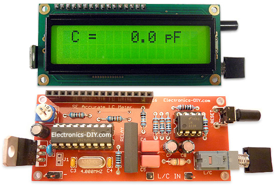
Accurate LC Meter
Build your own Accurate LC Meter (Capacitance Inductance Meter) and start making your own coils and inductors. This LC Meter allows to measure incredibly small inductances making it perfect tool for making all types of RF coils and inductors. LC Meter can measure inductances starting from 10nH - 1000nH, 1uH - 1000uH, 1mH - 100mH and capacitances from 0.1pF up to 900nF. The circuit includes an auto ranging as well as reset switch and produces very accurate and stable readings. |
|
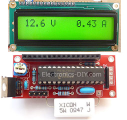
PIC Volt Ampere Meter
Volt Ampere Meter measures voltage of 0-70V or 0-500V with 100mV resolution and current consumption 0-10A or more with 10mA resolution. The meter is a perfect addition to any power supply, battery chargers and other electronic projects where voltage and current must be monitored. The meter uses PIC16F876A microcontroller with 16x2 backlighted LCD. |
|
|
|
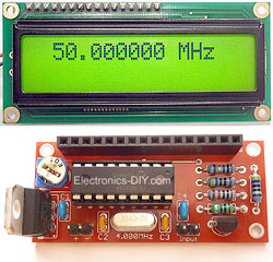
60MHz Frequency Meter / Counter
Frequency Meter / Counter measures frequency from 10Hz to 60MHz with 10Hz resolution. It is a very useful bench test equipment for testing and finding out the frequency of various devices with unknown frequency such as oscillators, radio receivers, transmitters, function generators, crystals, etc. |
|
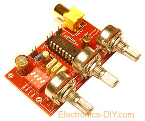
1Hz - 2MHz XR2206 Function Generator
1Hz - 2MHz XR2206 Function Generator produces high quality sine, square and triangle waveforms of high-stability and accuracy. The output waveforms can be both amplitude and frequency modulated. Output of 1Hz - 2MHz XR2206 Function Generator can be connected directly to 60MHz Counter for setting precise frequency output. |
|
|
|
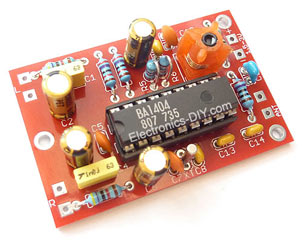
BA1404 HI-FI Stereo FM Transmitter
Be "On Air" with your own radio station! BA1404 HI-FI Stereo FM Transmitter broadcasts high quality stereo signal in 88MHz - 108MHz FM band. It can be connected to any type of stereo audio source such as iPod, Computer, Laptop, CD Player, Walkman, Television, Satellite Receiver, Tape Deck or other stereo system to transmit stereo sound with excellent clarity throughout your home, office, yard or camp ground. |
|
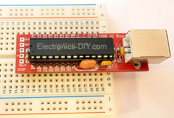
USB IO Board
USB IO Board is a tiny spectacular little development board / parallel port replacement featuring PIC18F2455/PIC18F2550 microcontroller. USB IO Board is compatible with Windows / Mac OSX / Linux computers. When attached to Windows IO board will show up as RS232 COM port. You can control 16 individual microcontroller I/O pins by sending simple serial commands. USB IO Board is self-powered by USB port and can provide up to 500mA for electronic projects. USB IO Board is breadboard compatible. |
|
|
|
|
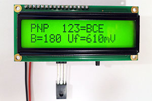
ESR Meter / Capacitance / Inductance / Transistor Tester Kit
ESR Meter kit is an amazing multimeter that measures ESR values, capacitance (100pF - 20,000uF), inductance, resistance (0.1 Ohm - 20 MOhm), tests many different types of transistors such as NPN, PNP, FETs, MOSFETs, Thyristors, SCRs, Triacs and many types of diodes. It also analyzes transistor's characteristics such as voltage and gain. It is an irreplaceable tool for troubleshooting and repairing electronic equipment by determining performance and health of electrolytic capacitors. Unlike other ESR Meters that only measure ESR value this one measures capacitor's ESR value as well as its capacitance all at the same time. |
|
Audiophile Headphone Amplifier Kit
Audiophile headphone amplifier kit includes high quality audio grade components such as Burr Brown OPA2134 opamp, ALPS volume control potentiometer, Ti TLE2426 rail splitter, Ultra-Low ESR 220uF/25V Panasonic FM filtering capacitors, High quality WIMA input and decoupling capacitors and Vishay Dale resistors. 8-DIP machined IC socket allows to swap OPA2134 with many other dual opamp chips such as OPA2132, OPA2227, OPA2228, dual OPA132, OPA627, etc. Headphone amplifier is small enough to fit in Altoids tin box, and thanks to low power consumption may be supplied from a single 9V battery. |
|
|
|
|
|
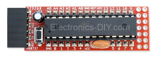
Arduino Prototype Kit
Arduino Prototype is a spectacular development board fully compatible with Arduino Pro. It's breadboard compatible so it can be plugged into a breadboard for quick prototyping, and it has VCC & GND power pins available on both sides of PCB. It's small, power efficient, yet customizable through onboard 2 x 7 perfboard that can be used for connecting various sensors and connectors. Arduino Prototype uses all standard through-hole components for easy construction, two of which are hidden underneath IC socket. Board features 28-PIN DIP IC socket, user replaceable ATmega328 microcontroller flashed with Arduino bootloader, 16MHz crystal resonator and a reset switch. It has 14 digital input/output pins (0-13) of which 6 can be used as PWM outputs and 6 analog inputs (A0-A5). Arduino sketches are uploaded through any USB-Serial adapter connected to 6-PIN ICSP female header. Board is supplied by 2-5V voltage and may be powered by a battery such as Lithium Ion cell, two AA cells, external power supply or USB power adapter. |
|
200m 4-Channel 433MHz Wireless RF Remote Control
Having the ability to control various appliances inside or outside of your house wirelessly is a huge convenience, and can make your life much easier and fun. RF remote control provides long range of up to 200m / 650ft and can find many uses for controlling different devices, and it works even through the walls. You can control lights, fans, AC system, computer, printer, amplifier, robots, garage door, security systems, motor-driven curtains, motorized window blinds, door locks, sprinklers, motorized projection screens and anything else you can think of. |
|
|
|