| |
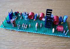
1Watt AM CW Transmitter for 10 Meterband |
|
In this project, you will make a simple 3-stage low-power broadcast-type circuit, using a crystal oscillator integrated circuit and an a collector modulated AM oscillator with amplifier. You can connect the circuit to the an electred microphone or amplified dynamic microphone. Using an electred microphone is shown (in gray) in the diagram below. (no amplified dynamic microphone has a to low output voltage to work. at least 100mv is needed). You could also add a LF preamp stage of one transistor to allow connecting a dynamic microphone directly.
You'll see that you can receive the signal through the air with almost any AM radio receiver. Although the circuits used in radio stations for AM receiving are far more complicated, this nevertheless gives a basic idea of the concept behind a principle transmitter. Plus it is a lot of fun when you actually have it working!
Remember that transmitting on the 10 meter band you'll need a valid radioamateur license!!
A wide range of different circuits have been used for AM, but one of the simplest circuits uses collector modulation applied via (for example) a transformer, while it is perfectly possible to create good designs using solid-state electronics as I applied here (T1 BC557).
The transmitter is build as a Colpitts Oscillator with a BSX20 transistor. HF-output of the oscillator is approx. 50 mW, depending on the supply voltage of 6 to 15 Volts. This is amplified by the BD135 and brings the power up to approx. 1 watt @ 12volts. The transmit frequency is stabilized with the 28Mhz crystal. A slight detuning of approx 1kc is possible when using a 120pF trimmer capacitor for C8. The oscillator signal is taken from the collector of T2 and guided to the input of T3 which output is lead via an L-filter and low-pass PII filter circuit cleaning up the signal pretty good and ensuring spectral purity. The oscillator is keyed by T1 and the morse key (S). By keying the morse-key T1 is not been used for modulation and is biased, hence lets T2 freely oscillate.

The oscillator uses a single coil and crystal. The coil is tuned to the output frequency, which may correspond to the crystal frequency, or a harmonic.
AM
Amplitude Modulation (AM) is a process in which the amplitude of a radio frequency current is made to vary and modify by impressing an audio frequency current on it.
This was the first type of modulation used for communicating signals from one point to another and is still the simplest to understand.
A radio frequency current has a constant amplitude in absence of modulation and this constant amplitude RF carries no information, i.e. no audio intelligence and is of no use to radio telephone (voice communication), but has application in morse code communication.
In its basic form, amplitude modulation produces a signal with power concentrated at the carrier frequency and in two adjacent sidebands. Each sideband is equal in bandwidth to that of the modulating signal and is a mirror image of the other. Thus, most of the power output by an AM transmitter is effectively wasted: half the power is concentrated at the carrier frequency, which carries no useful information (beyond the fact that a signal is present); the remaining power is split between two identical sidebands, only one of which is needed.
CW
CW is the simplest form of modulation. The output of the transmitter is switched on and off, typically to form the characters of the Morse code.
CW transmitters are simple and inexpensive, and the transmitted CW signal doesn't occupy much frequency space (usually less than 500 Hz). However, the CW signals will be difficult to hear on a normal receiver; you'll just hear the faint quieting of the background noise as the CW signals are transmitted. To overcome this problem, shortwave and ham radio receivers include a beat frequency oscillator (BFO) circuit. The BFO circuit produces an internally-generated second carrier that "beats" against the received CW signal, producing a tone that turns on and off in step with the received CW signal. This is how Morse code signals are received on shortwave.
Although this design is primarely designed for AM, it can be used for CW by keying S and so powering the oscillator. The amplifier (T3) is always fed with 12 volts Vcc and doesn't need to be switch off together with the oscillator.
If you only gonna use this transmitter for CW, then you can leave out the modulater section (T1). But remember that there is a 3 volt difference between Vcc and the voltage on the oscillator. So with modulator 12 Vcc is 9 volts on T2, without T1 ofcourse 12v also.
RF Oscillator
Is been carried out by T2 (NPN BSX20). This is the stage where the carrier frequency intended to be used is generated by means of Crystal Oscillator Circuitry or capacitance-inductance based Variable Frequency Oscillator (VFO). The RF oscillator is designed to have frequency stability (Xtal) and power delivered from it is of little importance, although it delivers 50mW@13v , hence can be operated with low voltage power supply with no dissipation of heat.
You could add a switch (not recommended, but if you do, use very short connections) to select different Xtal's (frequencies). You could also use a more effective diode-based switch I've build here. This hasn't got the problems with longer connections at all.
Injection of signal of an external tuneable oscillator to trigger T2 to oscillate is possible by removing the Xtal and connecting C8 to your oscillator.
Filter
RF power amplification is also done here and this stage is coupled to the antenna system through antenna impedance matching circuitry (L1/L3,C16,C18). Care is taken at this stage so that no harmonic frequency is generated which will cause interference in adjacent band (splatter) on other bands (L3/L4,C16...C20). This 3-element L-type narrow bandpass filter circuit and a lowpass filter for the desired frequency cleans out any remaining harmonic signals very efficiently.
Modulator
Is done by T1 (PNP BC557). Audio information is impressed upon the carrier frequency at this stage. Do to selective components circuits (R10, R11, C25, C3, C4, C5, C6, C7) the voice component frequencies are enhanced, whilest others are suppressed (bandwidth +- 3kc/side) keeping it approx. between HAM-radio specs.
Collector modulation is applied here. The efficiency isn't 100%, but it does keep the simplicity of the design intact.
Why over modulation is not desirable?..
Over modulation is not desirable, i.e. modulation should not exceed 100 %, because if modulation exceeds 100 % there is an interval during the audio cycle when the RF carrier is removed completely from the air thus producing distortion in the transmission.
Housing/shielding
The whole circuit needs to be mounted in an all-metal/aluminum case. If you're unable to obtain an all-metal case, then use a roll of self-sticking aluminum tape (available from your hardware store) or PVC box painted with graphite paint. Just make sure that all individual pieces of aluminum-tape (or the graphite paint) are conducting with each other. Works fine.
More power
You can connect the output to my power MOSFET based 10-meterband power amplifier wich should cranck up the power to approx. 6 watt. You'll find it here.
Mute: Use the transmitter with your receiver
If you put a relay, or better a transistor switch to mute your receiver (if equiped) you can easily make a QSO HI. A simple BC338, 2N2222 at pin a" with the base biased with a 100k resistor, emmitor at the gnd and the collector fed to your receiver's mute input works fine. Or you can use a 12v relay... Every time you PTT the transistor (or when using a relay, the switch) is "shortened" between the ground, hence muting your receiver (again; if your receiver has mute capabilities). This is shown in the diagram below.
Specifications
Peak Frequency range: 28Mc...30Mc
Output RF PEP power: approx. 1W@13v
AM modulated (CW if keyed)
Adjustable output impedance to 50 Ohms
Band-pass type harmonic L-filter + low-pass PII filter
Usable voltages: Vcc 10 - 15 volts
Average current: I= 120mA
Xtal oscillator, 28.xxx Xtal
Adjustable frequency of 2Kc (if C8 is replaced with a 120pF trimmer)
Injectable with external oscillator *see text
LF input +/- 100mV @ 1K
Schematic 10-meter band AM transmitter: fig1
Schematic for the 10-meter band HF transmitter
Parts list 10-meterband AM / CW transmitter
T1 BC557 (modulator)
T2 BSX20 oscillator (2N2219. BC109 works also, but little less power)
T3 BD135 amplifier (with heat sink isolated from the transistor)
T4 2N2222, BC338 mute
C1 = 100nF
C2 = 47uF/16v (tantal)
C3 = 2.2 uF/50v (changed in rev v1.5)
C4 = 33nF (polyester) (changed in rev1.5)
C5 = 10nF (polyester)
C6 = 47nF (changed in rev1.5 )
C7 = 4.7uF/50v
C8 = 10nF
C9 = 0...22pF (60pf for 27Mc)
C10 = 120pF
C11 = 56pF
C12 = 470uF/16v
C13 = 100nF
C14 = 47nF
C15 = 470pF
C16 = 6...40pF
C17 = 12pF
C18 = 120pF
C19 = 56pF
C20 = 100pF
C21 = 470pF
C22 = 100nF
C23 = 10pF*(added in revision v1.2)
C24 = 33nF (changed in rev1.5)
C25 = 0,47uF (polyester, added in rev1.5)
R1 3k9
R2 3k9
R3 3k3
R4 5k6
R5 1k2
R6 220
R7 12
R8 100k
R9 4k7* (added in revision 1.4)
R10 270 (added in rev1.5)
R11 390 (added in rev1.5)
Ls1, Ls2 = 470 1/2 watt carbon, 0,2 Cul turned 3 times over the entire length of the resistor (or 2.7uH inductor)
L1 = 0.8mm insulated copper wire, 8.5 turns close together, 7mm inside diameter
L2 = 0.8mm insulated copper wire, 12 turns close together, 6mm inside diameter
L3 = 0.8mm insulated copper wire, 13 turns close together, 7mm inside diameter
L4 = 0.8mm insulated copper wire, 7 turns close together, 7mm inside diameter
L5 = 100uH inductor (*added in revision 1.3)
L6 = 100uH inductor (*changed in revision 1.4)
Xtal fundamental frequency or overtone for your desired frequency (28...30Mc)
C4, C5, C6, C25 polyester film capacitors
top view Ls1,Ls2,Ls3
Revision 1.2
C21 added to prevent the oscillator from oscillating at 2e harmonic when not connected to the amp-stage. If the oscillator is coupled/connected (via C11) with the input stage of the amplifier as designed (even if the amp stage is not powered) 2e harmonic oscillations are prevented even without C21.
To resolve this issue (in any situation) C21 has been added.
C5 was missing from the partslist
R2,R3,R4 had slight diviated values from standard available resistors (thanks Medard from Switserland!)
Revision 1.3
To improve T2 BIAS: R5 was 2k2, now 1k2. L5 added (100uH)
To improve T1 BIAS: R1 was 4k7, now 3k9
C12 changed
Revision 1.4
Ls1 (former between C6 and C7) is replaced by 100uH inductor
R9 added to improve modulation
Revision 1.5 (May 2009)
R10, R11, C25 added, and C3,C4,C6,C24 changed values: to improve linearity
Note:
Always use a dummy load for testing and adjusting the transmitter!!!
Antenna's
It's important to use a correct designed antenna according to band you would like to operate, or at least use a good antenna tuner to match the antenna (protecting your transmitter and proventing harmonics/interference...). Several examples can be found on my website and all across the Web. A dipole is always a good alternative (total length = 150/freq - 5%).
The performance (distance relative to you RF power) of your antenna is as importent (if not more) as the RF power you transmit! A dummy load gives also a perfect 1:1 SWR, but you wont get any farther then the street you live in HI. Finally, athmospheric conditions (D-,E-,F-layers depending on the frequency you're using) is equally important to be able to make DX QSO's.

Related Links
Downloads
1Watt AM CW Transmitter for 10 Meterband - Link
|
|
|
| |
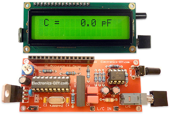
Accurate LC Meter
Build your own Accurate LC Meter (Capacitance Inductance Meter) and start making your own coils and inductors. This LC Meter allows to measure incredibly small inductances making it perfect tool for making all types of RF coils and inductors. LC Meter can measure inductances starting from 10nH - 1000nH, 1uH - 1000uH, 1mH - 100mH and capacitances from 0.1pF up to 900nF. The circuit includes an auto ranging as well as reset switch and produces very accurate and stable readings. |
|
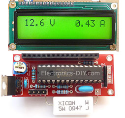
PIC Volt Ampere Meter
Volt Ampere Meter measures voltage of 0-70V or 0-500V with 100mV resolution and current consumption 0-10A or more with 10mA resolution. The meter is a perfect addition to any power supply, battery chargers and other electronic projects where voltage and current must be monitored. The meter uses PIC16F876A microcontroller with 16x2 backlighted LCD. |
|
|
|
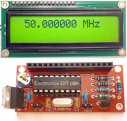
60MHz Frequency Meter / Counter
Frequency Meter / Counter measures frequency from 10Hz to 60MHz with 10Hz resolution. It is a very useful bench test equipment for testing and finding out the frequency of various devices with unknown frequency such as oscillators, radio receivers, transmitters, function generators, crystals, etc. |
|
1Hz - 2MHz XR2206 Function Generator
1Hz - 2MHz XR2206 Function Generator produces high quality sine, square and triangle waveforms of high-stability and accuracy. The output waveforms can be both amplitude and frequency modulated. Output of 1Hz - 2MHz XR2206 Function Generator can be connected directly to 60MHz Counter for setting precise frequency output. |
|
|
|
BA1404 HI-FI Stereo FM Transmitter
Be "On Air" with your own radio station! BA1404 HI-FI Stereo FM Transmitter broadcasts high quality stereo signal in 88MHz - 108MHz FM band. It can be connected to any type of stereo audio source such as iPod, Computer, Laptop, CD Player, Walkman, Television, Satellite Receiver, Tape Deck or other stereo system to transmit stereo sound with excellent clarity throughout your home, office, yard or camp ground. |
|
USB IO Board
USB IO Board is a tiny spectacular little development board / parallel port replacement featuring PIC18F2455/PIC18F2550 microcontroller. USB IO Board is compatible with Windows / Mac OSX / Linux computers. When attached to Windows IO board will show up as RS232 COM port. You can control 16 individual microcontroller I/O pins by sending simple serial commands. USB IO Board is self-powered by USB port and can provide up to 500mA for electronic projects. USB IO Board is breadboard compatible. |
|
|
|
|
ESR Meter / Capacitance / Inductance / Transistor Tester Kit
ESR Meter kit is an amazing multimeter that measures ESR values, capacitance (100pF - 20,000uF), inductance, resistance (0.1 Ohm - 20 MOhm), tests many different types of transistors such as NPN, PNP, FETs, MOSFETs, Thyristors, SCRs, Triacs and many types of diodes. It also analyzes transistor's characteristics such as voltage and gain. It is an irreplaceable tool for troubleshooting and repairing electronic equipment by determining performance and health of electrolytic capacitors. Unlike other ESR Meters that only measure ESR value this one measures capacitor's ESR value as well as its capacitance all at the same time. |
|
Audiophile Headphone Amplifier Kit
Audiophile headphone amplifier kit includes high quality audio grade components such as Burr Brown OPA2134 opamp, ALPS volume control potentiometer, Ti TLE2426 rail splitter, Ultra-Low ESR 220uF/25V Panasonic FM filtering capacitors, High quality WIMA input and decoupling capacitors and Vishay Dale resistors. 8-DIP machined IC socket allows to swap OPA2134 with many other dual opamp chips such as OPA2132, OPA2227, OPA2228, dual OPA132, OPA627, etc. Headphone amplifier is small enough to fit in Altoids tin box, and thanks to low power consumption may be supplied from a single 9V battery. |
|
|
|
|
|
Arduino Prototype Kit
Arduino Prototype is a spectacular development board fully compatible with Arduino Pro. It's breadboard compatible so it can be plugged into a breadboard for quick prototyping, and it has VCC & GND power pins available on both sides of PCB. It's small, power efficient, yet customizable through onboard 2 x 7 perfboard that can be used for connecting various sensors and connectors. Arduino Prototype uses all standard through-hole components for easy construction, two of which are hidden underneath IC socket. Board features 28-PIN DIP IC socket, user replaceable ATmega328 microcontroller flashed with Arduino bootloader, 16MHz crystal resonator and a reset switch. It has 14 digital input/output pins (0-13) of which 6 can be used as PWM outputs and 6 analog inputs (A0-A5). Arduino sketches are uploaded through any USB-Serial adapter connected to 6-PIN ICSP female header. Board is supplied by 2-5V voltage and may be powered by a battery such as Lithium Ion cell, two AA cells, external power supply or USB power adapter. |
|
200m 4-Channel 433MHz Wireless RF Remote Control
Having the ability to control various appliances inside or outside of your house wirelessly is a huge convenience, and can make your life much easier and fun. RF remote control provides long range of up to 200m / 650ft and can find many uses for controlling different devices, and it works even through the walls. You can control lights, fans, AC system, computer, printer, amplifier, robots, garage door, security systems, motor-driven curtains, motorized window blinds, door locks, sprinklers, motorized projection screens and anything else you can think of. |
|
|
|